Results 1 to 17 of 17
  1. #1
    Contributing Member RussMcB's Avatar
    Join Date
    03.19.02
    Location
    Palm Coast, FL
    Posts
    6,680
    Liked: 553

    Default Oil System Venting

    I'm building a car and would like to hear about folks's oil tank/engine/catch tank venting.

    My car has the original oil tank (Ralt RT-4) with two breather ports. One looks to be for vapors entering the oil tank and one for exiting (that's my hunch based on the baffling I can see).

    My engine (Suzuki GSXR Gen 2) has a breather port in the back of the engine. I think it was where the reed valves were. Now it has a -8AN fitting.

    I'm assuming I should run a hose from that port to my oil tank, then use the other port to the catch can.

    Sounds simple, but I've heard two things that make me think about other options:

    1. A buddy with a similar layout took his newly built car out and it pushed a lot of oil into the catch can. We've had a dozen theories about the cause, but no definite known cause. He's made several changes and will test them in a few weeks.

    2. I've heard that George Dean has suggested using the clutch cover's oil filler cap as a vent (return line?), and perhaps some of the oil/vapors coming out of the oil tank can be persuaded into returning to the engine, rather than to the catch can.

    I kind of like that idea, but I'm not sure about where the high and low pressures are. For instance, piston ring blowby might cause the crankcase to be pressurized, but the sump pumps might be sucking enough to cause a vacuum.

    Regardless, the oil tank will need to vent that pressure, so there will definitely be vapors/vents leaving the oil tank. It would be great if the line from the oil tank to the catch can could have a tee or something to encourage vented oil back into the engine. I thought about using the oil fill port for that, but with a spinning clutch plates, will oil be slung out, making that a bad place for a return line?

    Hope all that makes sense, and I know I'm probably overthinking it, but I want to understand the flow of the oil/vapors. Plus, I figured many of you have similar cars with vent plumbing that works great.

    Thanks, guys.
    Racer Russ
    Palm Coast, FL

  2. #2
    Senior Member ghickman's Avatar
    Join Date
    04.20.07
    Location
    Alpine California
    Posts
    1,192
    Liked: 273

    Default

    Russ
    Is this a GSXR1000 with a Dry Sump?
    Gary Hickman
    Edge Engineering Inc
    FB #76

  3. #3
    Senior Member
    Join Date
    09.12.02
    Location
    Detroit area
    Posts
    1,270
    Liked: 141

    Default

    Russ - I bought an old Ralt tank just to cut open and see what was inside. Can send you pics if you like. You'll be baffled by the baffles - there is none. Derek

    Just remembered I already have some pics -
    Last edited by dereklola; 03.24.17 at 12:33 AM.

  4. #4
    Contributing Member RussMcB's Avatar
    Join Date
    03.19.02
    Location
    Palm Coast, FL
    Posts
    6,680
    Liked: 553

    Default

    Quote Originally Posted by ghickman View Post
    Russ
    Is this a GSXR1000 with a Dry Sump?
    Almost. GSXR1300 Hayabusa (yes with a dry sump). My guess is they're basically the same.

  5. #5
    Senior Member
    Join Date
    01.11.05
    Location
    Zionsville, Indiana
    Posts
    3,169
    Liked: 1397

    Default

    I have build a few oil tanks over the years. Here is what I have learned:

    1. Tall is good and taller is better. You will need a total volume that is three times the amount of oil you want in the tank. Say you want 4 quarts in the tank, you will need a tank that has 12 quarts volume, minimum.

    2. Round tanks are the easiest to build and work best. Any other shape will create challenges in managing the oil. You have to account for both lateral surge and braking surge. Either has the potential to un-port the oil pickup in the bottom of the tank and that leads to oil starvation problems. Round tanks that have taper down at the bottom or have a trench for the oil pickup are the best.

    3. To vent the oil tank, I like to have a tube that extends down from the filler cap about 1/3 the height of the tank. I then have a vent tube that opens into this tube under the filler cap.

    4. I vent the engine into the tank in the same area that I have the oil return to the tank. Just easy to do it this way.

    5. For each tank design and engine combination, there will be some oil level at which you will start venting oil out the breather.

    6. In the most recent designs for oil tanks I have done, I have the oil filler and the oil return as high as I can. That is close to the top of the engine. These tanks have been rectangular in the bottom section and it has taken a lot of baffling to get the tanks to function correctly.

    The round tanks on the Zink Z10 were the easiest to make and worked the best. They were round, close to 15 inches tall, and maybe 6 inches in diameter.

  6. The following members LIKED this post:


  7. #6
    Contributing Member
    Join Date
    10.08.06
    Location
    San Jose, Ca
    Posts
    714
    Liked: 89

    Default

    Russ, reed valves are on top of the valve covers in little rectangular cutouts under a two bolt cover. They T into a ECU controlled solenoid valve, and get air from a hose connected to the airbox.

    The vent port is located above the transmission (at least the GSXR 1K) on the top of a squarish looking box.

    Back in the old days we used to connect the reed valves to that port to help scavenge the crank case. Problem was if you pushed any oil out the vent port it went right into the exhaust system and instant smoke cloud. Needless to say thats a big no no these days. If you still have the reed valves operational in the motor its real easy (and no cost) to modify them to be blocked off.

  8. #7
    Senior Member
    Join Date
    09.12.02
    Location
    Detroit area
    Posts
    1,270
    Liked: 141

    Default

    Steve - great info - as usual.

    Two questions -
    - when you say "tube that extends down from the filler cap" I assume you mean welded to the tank (ie. not welded to the filler cap)
    - I'm planning to make a tank soon with bigger bottom - would round be better than square? - upper section 6" diam x 12" high and bottom section 8- 9" diam x 6" high?

  9. #8
    Contributing Member RussMcB's Avatar
    Join Date
    03.19.02
    Location
    Palm Coast, FL
    Posts
    6,680
    Liked: 553

    Default

    Thanks, guys. Responses much appreciated.

    Derek - Yes, I remember your cut-up tank. Very helpful. The "baffles" I was referring to were really just the way the tubes were positioned in the tank.

    (picture removed. I just realized it was a picture of the TOP of the tank, tuned upside down. Sheesh. I'm a bit dense sometimes)

    I mispoke about the "reeds" in my original post. Sorry for the confusion. My cam cover is blocked off where the reeds were. I was referring to the thing above the transmission. I'm not sure what its original purpose was, but mine has been cut down a bit and then a -8an fitting added (by PO):


    So, has anyone heard about a vent port located at the oil fill plug on the clutch cover? I *think* I heard someone say that was a GDR suggestion, but I could be mistaken.
    Last edited by RussMcB; 03.24.17 at 1:44 PM. Reason: Added pictures

  10. #9
    Senior Member
    Join Date
    01.11.05
    Location
    Zionsville, Indiana
    Posts
    3,169
    Liked: 1397

    Default

    Quote Originally Posted by dereklola View Post
    Steve - great info - as usual.

    Two questions -
    - when you say "tube that extends down from the filler cap" I assume you mean welded to the tank (ie. not welded to the filler cap)
    - I'm planning to make a tank soon with bigger bottom - would round be better than square? - upper section 6" diam x 12" high and bottom section 8- 9" diam x 6" high?
    Correct. The tube is welded in the tank. On recent tanks, I have a double tube on top ot the tank. One inside the other. The filler opens to the inner tube and the oil return and engine vent plumb into the outer tank.

  11. #10
    Contributing Member
    Join Date
    10.08.06
    Location
    San Jose, Ca
    Posts
    714
    Liked: 89

    Default

    Russ, I have seen the fill plug port over the clutch used as a vent. This was in a dry sump configuration.

    If you pull off the cover (no idea why its machined) you will see that it has a labyrinth to attempt to allow the oil to separate out from the air being vented.

  12. The following members LIKED this post:


  13. #11
    Contributing Member farrout's Avatar
    Join Date
    08.19.05
    Location
    Sanibel, FL
    Posts
    362
    Liked: 41

    Default

    In my AMAC with a GSXR 1000 and dry sump configuration, the vent hose from the cover on the engine went into the top (above the static oil level) of the sump tank. There was a vent in the top of the sump tank into the catch can. My reed valve ports were covered over. This was the system that George Dean set up for the car with his built engines.

    In my Stohr with a GSXR 1000 and wet sump configuration, the vent hose goes into the catch can directly. The reed valve ports are tied to each other.

    In both cases, the vent hose configuration allows air to be vented or sucked in as needed. If you overfill the oil in either system, the catch can tells you that you have done so.
    Last edited by farrout; 03.25.17 at 2:41 PM.
    Craig Farr
    2006 Stohr WF1 P2
    FARROUT Racing

  14. #12
    Contributing Member
    Join Date
    10.08.06
    Location
    San Jose, Ca
    Posts
    714
    Liked: 89

    Default

    Quote Originally Posted by farrout View Post

    As this is a stock engine, the reed valves feed back into the valve cover.
    Stock or built doesn't matter, these ports need to be blocked or you will continually backfire in the exhaust.

  15. The following members LIKED this post:


  16. #13
    Contributing Member glenn cooper's Avatar
    Join Date
    02.18.06
    Location
    atlanta, ga
    Posts
    3,063
    Liked: 136

    Default

    Looks like there might be the need for a little bit of clarification:
    The dry sump setup that sees the top of the oil tank connected to the clutch cover oil fill port is primarily to allow the total oil capacity of the system to be improved.
    Extra insurance in a place like the Carousel at Rd America with a very long duration lateral G, etc...
    The standard "top of engine crankcase, above transmission" breather vent is just that - allowing pumping pressure from the pistons a place to go - restrict that too much on a wet sump system, and you are liable to push out the output (sprocket) shaft seal, which is only a press in from the outside, affair.
    I have seen dry sump setups with a much smaller ID spigot on the crankcase/trans breather, but they are pulling vacum the whole time.
    On my ZX10R in the RFR F1000, I did not have a modified / smaller vent ID.
    I saw a (highly avoidable) problem last race at Rd Atlanta, where a car had filled it's oil puke tank to overflow and beyond, due to operator error and overfilling the system by pretty much the volume of oil that got expelled.
    The drysump setups on the GSXR seem to run right about 4.5 qts TOTAL, which should get the oil to the top of the window warmed up and held at 4k rpm.
    Most wetsump setups I have seen are right around 6.5 qts - which of course is dependent on tank size for sure.
    The Speedway tank I have used, and the RFR tank were NOT designed real well, which really blew my mind - the Speedway tank was a 2 pc affair, split in the middle with a band clamp for ease of cleaning, but the plates did not even extend radially to the inner wall of the tank - essentially negating the whole de-aerating process.
    On the RFR, there was only one plate in a one piece welded up tank, and the oil inlet was located BELOW the plate!
    On the RFR there were two vents at the top of the tank - in wet sump guise, the top of trans vent went to the lower tank inlet, and the upper went to a puke can, which then had a hose to the rear of the chassis.
    On the RFR with the drysump getup, the trans vent went to a catch tank, the upper oil tank outlet went to the clutch cover, and the other, slightly lower oil tank vent was capped.
    I can't believe I am gonna do this, but I have to disagree with Steve on the tank size requirement, where he mentions needing a 12 qt tank if you plan to store 4 qts, there.
    This might be a thing, I suppose in a sedan, with a 4 gallon Peterson Flowerpot tank, but the tall slender 6 qt. tanks I have run in my Nova Dieman, and the RFR all worked fine.
    In fact when I built the Nova Dieman, I just chose a 6" diam, because that is what wpuld fit between the rear damper rockers (!), and tall as could fit under the engine cover, and was able to mount it directly behind the engine, which ensured the shortest flow path to the inlet.
    No engineering degree (!), it just made sense.
    About the only thing I didn't do, due to ignorance, was up the ID of the line from the tank to the pan/eng oil pump pickup. As big as you can make it is the AN size you want, and definitely a hard line at this point, or a very stiff wall hose, if not SS braided hose. I have seen the soft fabric hose used on suction side like that and it just ain't a good idea.
    (Holy crap, still kinda freaking out I countered Steve's advice - Breathe... keeeeep breathing...)

    I probably have more thoughts on this, but my fingers are tired!

    Coop out.

  17. #14
    Senior Member David Locke's Avatar
    Join Date
    11.19.02
    Location
    Indiana
    Posts
    445
    Liked: 175

    Default

    Quote Originally Posted by glenn cooper View Post
    The drysump setups on the GSXR seem to run right about 4.5 qts TOTAL, which should get the oil to the top of the window warmed up and held at 4k rpm.
    Most wetsump setups I have seen are right around 6.5 qts - which of course is dependent on tank size for sure.
    Coop, I believe these are reversed; ~4.5 qts. is what I run with my GSXR wet sump.

  18. #15
    Contributing Member farrout's Avatar
    Join Date
    08.19.05
    Location
    Sanibel, FL
    Posts
    362
    Liked: 41

    Default

    Quote Originally Posted by 10rmotor View Post
    Stock or built doesn't matter, these ports need to be blocked or you will continually backfire in the exhaust.
    Thanx. My memory was faulty. The ports have the stock covers but they are hosed to each other not back into the engine separately. Is that sufficient or do they actually need to be blocked?
    Craig Farr
    2006 Stohr WF1 P2
    FARROUT Racing

  19. #16
    Contributing Member
    Join Date
    10.08.06
    Location
    San Jose, Ca
    Posts
    714
    Liked: 89

    Default

    Quote Originally Posted by farrout View Post
    Thanx. My memory was faulty. The ports have the stock covers but they are hosed to each other not back into the engine separately. Is that sufficient or do they actually need to be blocked?
    I think what you have is fine, I've seen that done before but I like to remove stuff whenever possible, so what I do is modify the reed valve assembly. Remove the reed valve plate from the cover, unscrew the curved reed valve support and flip that support over so that it presses the reed valve closed. Then reinstall the plate with the reed valve and support up instead of down.

  20. #17
    David Arken sccadsr31's Avatar
    Join Date
    04.24.07
    Location
    San Jose
    Posts
    272
    Liked: 83

    Default This is Kawasaki not Suzuki

    This is a Kawasaki not a Suzuki, but it is worth re-posting. The Gen 1-3 Kawasaki have a breather in roughly the same place as the GSXR. My wet sump engines kept pumping oil out the breather, some engines more than others. After a particularly bad weekend I spent the time to study the internal breathing system.
    Right below the external breather tube is a sealed chamber.
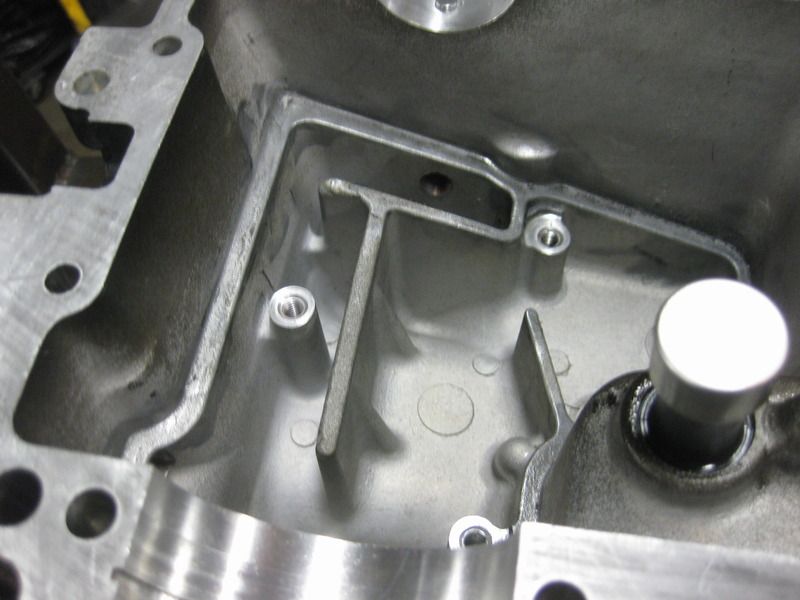
    After removing this cover which is a challenge the way Kawasaki has glued it in place with there super rtv bond there is a chamber with 2 8mm inlet holes;
    1 hole exits behind the flywheel in the clutch area.
    2 hole runs through the case to the bottom of the oil pan and exits where it would be about 5mm above the bottom of the oil pan. This means it is always covered by the oil unless the engine is virtually out of oil.


    In order for this engine to push a quart of oil out of the external engine breather this chamber has to be completely full and the forces at work have to be overcoming the exit hole behind the flywheel. Now I do not claim to completely understand this however I figured this chamber needed more venting so I opened it up to the case around the transmission and the crankshaft.
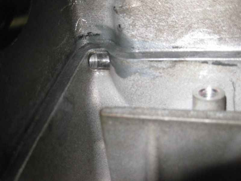
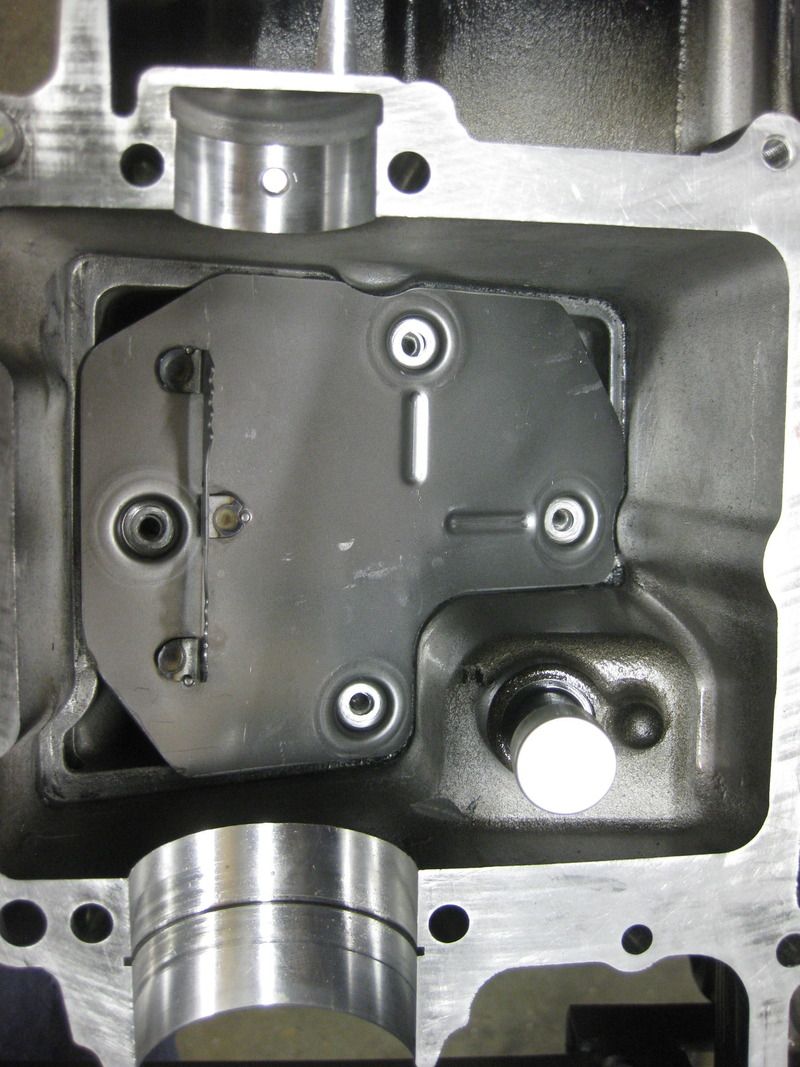
    The result has been no oil in the catch tank and I was able to reduce the amount of oil in the engine by about 1/2 a quart.

    My suggestion is crawl through the Suzuki engine and see if it needs some relief internally.

    David

Thread Information

Users Browsing this Thread

There are currently 1 users browsing this thread. (0 members and 1 guests)

Posting Permissions

  • You may not post new threads
  • You may not post replies
  • You may not post attachments
  • You may not edit your posts
  •  


About Us
Since 2000, ApexSpeed.com has been the go-to place for amateur road racing enthusiasts, bringing together a friendly community of racers, fans, and industry professionals. We're all about creating a space where people can connect, share knowledge, and exchange parts and vehicles, with a focus on specific race cars, classes, series, and events. Our community includes all major purpose-built road racing classes, like the Sports Car Club of America (SCCA) and various pro series across North America and beyond. At ApexSpeed, we're passionate about amateur motorsports and are dedicated to helping our community have fun and grow while creating lasting memories on and off the track.
Social