Originally Posted by JJLudemann

Wrenches? In Kentucky, the only tools allowed are hammers - and if it doesn't fit, you use a bigger hammer!


Wrenches? In Kentucky, the only tools allowed are hammers - and if it doesn't fit, you use a bigger hammer!


Wow, has it really been that long since I've posted? I really had no idea. I've been busy, busy, busy. Since the last update I've laid up the body, built and installed the suspension rocker arm mounts and shock/spring mounts, had parts plated and anodized, welded in the control arm mounts, had a radiator custom built, built the upper control arms, tierods & pushrods, built & installed the steering rack mount, steering rack extensions, seat bottom, steering column mounts, and the entire steering column up to the steering wheel, modified and assembled the wheel hubs, stub axles, brake hats, spacers, brake discs, brake calipers, wheels and lug nuts, built a workshop gantry crane, made an upper right frame tube removable, and built the engine mounts. The engine is now in place. It starts to add up when you look at it that way, but while doing it, it feels like the hours and days just disappear. Also had a problem where my partner was attacked and her arm broken, so I've had to play nurse and take care of a lot of things. Don't worry, the guy's in jail now, heh heh.
I've encountered a problem due to the fact that Wilwood doesn't publish the offset dimension for their vented brake discs, so that the vented disc is off-center (3.5mm) from the center plane of the caliper. One way to solve the problem is to convert the front brakes to solid rotors. Have solid front rotors proven adequate in F1000 racing? And if so, is the spacer between the two halves of a Wilwood Forged Dynalite caliper a user-serviceable component? I.e. can I remove it myself? If I were in the US I'd just point and click some new calipers, but here it's a wee bit more complicated.
Thanks,
-Jim

Solid rotors are fine, I've used both. Vented rotors in my opinion are of little benefit and the weight penalty is a no go for me.
Yes you can remove the spacers from the Wilwood calipers.
Gary Hickman
Edge Engineering Inc
FB #76

Thanks for the update Jim. It is really impressive what you have been able to do. For your front shocks, you have a black bolt-on "cross-beam" that spans the frame. I haven't seen something like that before and was curious what your motivation was for using that approach to mount the shocks? Keep up the good work!
Thanks. That's great to know in advance! Another question along those lines: Can I laser-cut a rotor from sheet steel of the appropriate thickness, and then maybe turn it on the lathe to get it good enough? Or does it have to be A) cast iron and not steel or B) ground on a big machine I don't have rather than turned on a lathe?
-Jim
You can use mild steel plate, but it will have half the Cf of cast iron. Better to get some 80-55-06 ( Ductile 80) blanks saw cut from the appropriate diameter bar stock and make your rotors from that instead. Ductile 60 would work also. Grey 40 would work, but will be a lot more prone to heat-stress crack.
Lathe turning is fine. You just want to keep the faces as parallel as possible - less than .003" runout - and the feed rate low ( .002 per rev or so). The final surface finish cam be improved a bit by sanding while still in the lathe if you want.
Another option is find a passenger car rotor and modify it. Some of the late 70's-80's vintage Japanese cars had solid rotors that have a very shallow hat that can be easily machined off and turned into a purpose built formula car rotor.
I've done this many times and it works well.
Gary Hickman
Edge Engineering Inc
FB #76
When I studied the loads applied by the springs & dampers on that crossmember it became clear a tube would need a lot of additional bracing, to the point where the tube became irrelevant and it was easier to laser-cut and fabricate the part. Then, as a result of comments received on this forum, I decided to make the engine removable from the top instead of the bottom of the car so that crossmember had to become removable. "Laser-cut, bend, weld" has been a good method to use the materials and subcontractors available here and to keep costs down.
-Jim
There's always something, huh? I hadn't thought about the difference in coefficient of friction; I was mostly thinking about heat conduction and cracking. Don't know if I have a chance of finding Ductile 80 or 60 around here. Thailand hasn't really discovered the Internet yet, unless you count "Line".
Last time I was at the auto recyclers I poked around a bit but didn't see anything usable. That's a good idea, though. I'll keep my eyes open.
Thanks,
-Jim
I was just rereading the GCR and was thinking about this:
9.4.5.E.3: Roll cage or chassis design shall prevent engine intrusion into the driver compartment.
What I've designed so far is shown in the attached image, but I was thinking this might not be adequate and now's the time to fix it before I weld in the fuel tank and bulkhead skins. Right now I have only one 1" x 0.050" horizontal round tube across the opening, along with a fully-welded skin of 0.040" steel in accordance with the rules allowing stressed panels in the roll hoop bulkhead. The lower opening will have another 0.050" steel panel across it forming the back of the fuel tank. I would like to fully weld the fuel tank skin also but I think a double-walled stressed skin might be illegal. In the photo you can also see the left-side shoulder harness attachment point, which is made of 1/8" steel welded to the tubes above and below. This will be duplicated for the right shoulder.
So can I fully weld the fuel tank skin to make a double-walled stressed-skin panel and would that be enough, or should I weld in some additional verticals/horizontals/diagonals? I'd appreciate any photos or info of standard practice in this area.
Thanks in advance,
-Jim
I would put a "V" brace in the lower half of the roll bar bulkhead. Start at the bottom corners and go up to the middle of the cross tube. You could add rossette welds from the fire wall to all the cross tubes.
This will add to the beam strength of the roll bar bulkhead.
I'm not getting why you would need a double-walled skin? Weld the .050 fuel cell back to the front side of the bulkhead tubes, and it will also serve as your lower firewall. No need for a second skin.
I was thinking the double skin would be great for thermal insulation of the fuel tank (I could even fill the hollow with shredded fiberglass or something) and as ballistic protection for the fuel tank in case of an engine explosion. Is that overkill? I don't really have a feel for the worst possible case. Has anyone ever seen a firewall even dented by an engine explosion?
-Jim

This is exactly how I did the skin's on the Speads. Definitely not a overkill... Yes dents are possible, I've seen it happened on multiple occasions.
Last edited by BURKY; 04.12.14 at 7:10 AM.
Does everybody just use the stock gear shift link arm? That's the 2-3" arm with the internal spline that slips onto the gear shift shaft on the left side of the engine. I can't find one anywhere. I would think one of the air shifter companies would make a billet aluminum one, but can't find that either. I know enough to say it's part# 25510-40F00, compatible with 04-05 GSX-R600 and GSX-R750, and with 05-08 GSX-R1000 bikes. Ebay has arms for older bikes, newer bikes, and bigger bikes, so does anybody know if the splines are compatible with any other year/model/displacement?
Thanks,
-Jim
I made my own broach and splined several aluminum levers myself. Fairly easy to make yourself a broach if you have an old blown up engine laying around. Use the old shift shaft as a donor and machine a taper in it so you can push it thru with a small press.
Or you can go to bikebandit.com and simply order up a shift lever, cut the splined portion off, fab up a lever and weld it on. All the Suzuki powerplants use the same metric 90 degree serrated spline.
Gary Hickman
Edge Engineering Inc
FB #76
OK, great. The other ones are easy to find on Ebay. So bikebandit.com is the hot setup for mailorder OEM parts, I take it? Ordering is getting easier as the mailman is now a family friend, and the last parts came through from the US with only a 10% duty + 7% VAT.
Thanks,
-Jim
I just picked bikebandit.com because they're about 15 miles from my shop and I figured if you are having it sent to Thailand that California is just that much closer.
If you have trouble determining which one is correct let me know and I will point you in the right direction.
How's the car coming along?
Gary Hickman
Edge Engineering Inc
FB #76
It's coming along well. It's a roller, with engine, brakes, transmission, side panels, radiator, oil cooler and steering all in. Or at least they've all been in at one point. What's left is the gas tank, pedal cluster, shift lever, air ducting and all the fuel, brake, oil, water, and clutch lines & electrical. I think I've got the wiring harness all figured out but not installed. What looked daunting at first now looks perfectly reasonable...
I like your idea of how to make a broach for the gear linkage arm, but I don't have a spare gear change shaft. It'll be on my list for next time.
-Jim

Great progress & reporting Jim
Your lift plates incorporate a series of pickup holes that allow one to suspend the GSXR at several different angles in side elevation. My curiosity implores me to ask:
Could you add side elevation pics of those suspension angles to your build report?
- and/or -
What is the ~COGH for your GSXR?
Keep it up!
Inquisitive Rick
Last edited by Rick Kean; 06.29.14 at 3:16 PM. Reason: add pic
> Your lift plates incorporate a series of pickup holes that allow one to suspend the GSXR at > several different angles in side elevation. My curiosity implores me to ask:
> Could you add side elevation pics of those suspension angles to your build report?
> - and/or -
> What is the ~COGH for your GSXR?
> Keep it up!
Hi Rick,
Sorry for the long delay in replying. My mom passed away and I haven't felt like communicating much.
Attached is a straight-on view of one of the engine lifting plates, corrected as well as I can for perspective and lens distortion. It'd be better to just scan the plate, but it's currently lifting the engine. Dimensions are 228 x 100mm, and you can scale the hole positions from that. I don't have a drawing for this as I just winged it in the machine shop. As you can see I'm using the last adjustment hole, so you might want to place the column of holes a little closer to the engine mounting holes. I didn't measure the angles using the other holes, but that would be a good way of finding the COG, wouldn't it...
-Jim
Hi all,
I've been quiet for a while but I've been working continuously. I finally got caught up on updates to my blog. This was a daunting task, which partly explains why I put it off for so long:
Fabricating GSX-R1000 Engine Mounts
Removable Engine-Compartment Frame Rail
Fabricating the Differential Mounts
Mounting the Rear Sprocket
Building the Axle Halfshaft Extensions
Mounting the Side Impact Panels
Welding on More Random Jingly Bits
Fabricating the Fuel Tank
Building the Firewall
Building the Floor Pan, Floorpan, Belly Pan, Whatever
Paneling the Cockpit
Attaching the Body
Fabricating the Shifter Assembly & Linkage
Fabricating the Pedal Cluster
Shaping the Dashboard
Painting the Frame
So now I'm in the final (hopefully) assembly phase. Things are getting bolted on with lock nuts and Locktite and I'm having a new experience: the car's so clean I have to wash my hands BEFORE I work on it!
Enjoy!
-Jim

sorry to learn of your mom's passing
your craftsmanship is superb

Your pedal assembly is a true work of Art ! As is the entire car !
"An analog man living in a digital world"
Good to see you're still at it! Godspeed to you & yours.
"You GO Now"
Rick
"You GO Now"
Rick
Thank you, on both counts. For craftsmanship, I rely on a principle I read a long time ago on another thread about home-built cars: If it bothers me, I fix it.
-Jim
Thank you very much. The pedal assembly is probably a little over the top, but I decided to see how far I could go with the tools available to me. I'm happy with the result.
-Jim
Don't worry, I'm not going to quit. I do get slow sometimes, though...
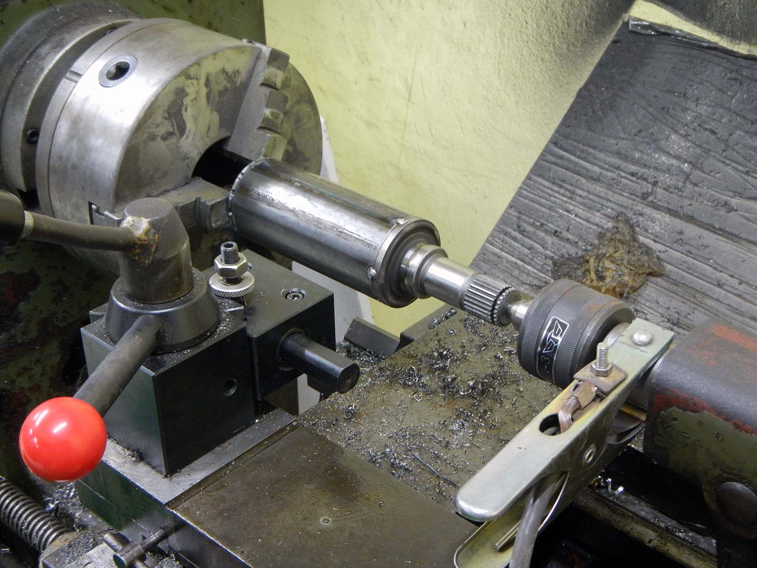
The tailstock bearings have never been great, so I'd say they're just as crappy now as they were before. Now that you've pointed it out, next time I'll put the clamp directly on the stub axle. I came across the paperwork the other day and I only paid about $3000 for the lathe, so it's almost a consumable for this project. The history of everything on this project seems to be I start out cheap and end up spending way more than I planned.
-Jim
I have a GSX-R1000 wet-sump oil pan I bought through George Dean, and there doesn't seem to be a provision for an oil pressure relief valve. Is it just deleted, or is there something I don't understand? If it's deleted, how does that work?
Thanks in advance,
-Jim
Jim
The stock 07/08 pan had the pressure relief valve attached to the pan. When you install the aftermarket pan the relief valve actual gets transferred from the stock pan to the new pan and slips into the block and hangs down into the aftermarket pan. There should be a counterbore in the new pan where the stock relief valve would be.
Send me a picture of what you have and I can identify it and solve the mystery.
Gary Hickman
Edge Engineering Inc
FB #76
Thanks a lot for the quick reply. It's after midnight here, but when I get back out there tomorrow I'll see if I can figure it out. Should be easy with your explanation. If I correctly understand what you're saying, whoever designed the pan is clever.
-Jim
Jim
The stock pan had a communicating port where the relief valve was located. The billet A/M pans don't require that communicating port hence the relief valve was moved up to where it would normally reside. This is the way the previous Suzuki pans where done.
It was a packaging issue in an effect to tighten things up on the bike and maybe lower the cg
Gary Hickman
Edge Engineering Inc
FB #76
Ah, I see. I was thinking they'd come up with something better than the Suzuki factory engineers, which would be impressive.
Anyway, I think I've got it figured out. Rather than posting a photo, I made a tutorial on my blog:
How to Install a Low-Profile Oil Pan on a 2007-2008 K7 GSX-R1000 Engine
Did I get it right? If not, it's easy to change.
Thanks,
-Jim
Jim
Ok everything looks good to me as far as the install goes however I see something that looks alarming to me.
The pan you got from GDRE has the pickup at the rear of the pan. This was found to be problematic about 5 years ago and has since been moved to the front of the pan.
Here is a link to the Edge Engineering site that has a good top view picture of how a proper forward facing pan should look. http://edgecnc.com/products-for-sale.html
In my opinion I would change the pan to a newer style. Less chance of having Oil Pressure drops that can lead to engine failures.
Last edited by ghickman; 12.07.14 at 10:54 PM.
Gary Hickman
Edge Engineering Inc
FB #76
Well, isn't that special. I'm glad we went through this exercise. So it appears there are three generations of oil pan. Gen. 1 is shown in the first photo below, and has a short oil pickup box at the back. I bought this one about four years ago through George Dean. Gen. 2 is shown in the second photo, with a longer oil pickup box. Dean sent me this one in August 2012 as a free replacement for my Gen. 1 pan which was sent in error. Gen. 3 is as shown in your link, with the oil pickup box moved completely to the front. The photos on my blog are a little confusing as they were taken in the process of replacing the Gen. 1 pan with the Gen. 2 pan. I didn't think anyone would notice, but this forum is soooo sharp I should have known better.
Has anybody actually seen oil pressure drops with the Gen. 2 pan, or was the Gen. 3 pan more of an intellectual exercise to redesign it from scratch the right way? I ask because Rilltech looks to be still selling the Gen 2 pans, revised for shorter bolts (Gen 2b?):
http://www.rilltechracing.com/products/
It looks like "pop off the old pan and pop on a new one" may extend to a month-long project
Thanks & sorry to be such a pain,
-Jim
Jim
The pan pictured on the right of your latest post appears to have the forward facing wall of the trap door box moved forward. Does the pickup that you have for this pan face forward?
The picture of the pan on the Edge CNC site dates clear back to 2009. I believe the pan that Rilltech sells now looks similar.
We flipped ours around to face forward simply because we saw pressure dips under braking.
There are old threads on Apexspeed talking about this very subject.
Gary Hickman
Edge Engineering Inc
FB #76
Yes, my current (Gen 2) pan has the forward facing wall of the trap door box moved forward. Yes, the pickup I have for my Gen 2 pan faces forward. In the attached photo, forward is to the left. So the pickup point is just behind the flappy door on the front of the trap door box. But the pickup point is not as far forward as your design would allow. Mine looks like the Gen 2 pan in the photo on the Rilltech website.
Initially I received a forward-facing (Gen 2) pickup with the Gen 1 pan (designed for the rearward-facing pickup?). These two parts are incompatible with each other. That's where some of the confusion is coming from.
Thanks again,
-Jim
Jim
Mystery solved...You've got one of the improved pans then.
Gary Hickman
Edge Engineering Inc
FB #76

...and the oil pressure relief valve goes "o" ring side in first (up) in the location that in the pic currently has the little double o ringed collar piece that connected to the stock pan tunnel.
It's directly rearward of the oil filter.
Go ahead and measure from the bottom of the crankcase to the bottom of the pickup, then compare to the depth of the wet sump pan.
I believe the gap you are wanting here is about 3/16".
Sometimes the pickups are not long enough and you give up capacity that you shouldn't have too.
There are currently 1 users browsing this thread. (0 members and 1 guests)
 Posting Permissions

 Reply With Quote