Results 1 to 28 of 28
  1. #1
    Senior Member rodorico83's Avatar
    Join Date
    07.17.13
    Location
    Madrid, Spain
    Posts
    146
    Liked: 8

    Default engine mounts-tube brackets design

    Hi guys,
    Im starting to design the engine tube mounts for my lola. I have some ideas on mind that i would like to cross check with you.
    Some background here, This installation was based on another lola in which this engine was installed.

    Please correct if any affirmation i do is not valid or you do not think like that


    • Top mounts:

    The top mounts on the other lola were in steel, and the main stud is threaded into the bracket and does not enter into the bulkhead monocoque. 2 brackets on each side were installed the original for the zytek engine (alloy bracket) and on top a new one in steel.


    I do not see any benefit on reusing the old bracket so i will not put both brackets on each side, I will make one per side.
    Note the extension on the side that fix bracket into the tube sides.

    This is the tube of my lola on one side. old main stud and 4 support 1/4 bolts


    Still need to check if possible to thread tube for new engine studs, as on right side of tube there is a big bore to pass the wiring loom and it might be at same location as where stud should go. see pic (highlighetd in red)


    Will give more strength to place a thread insert in the monocoque and fix stud on it instead of threading and fixing into bracket ??
    what about stud threaded into bracket and then inserted into the tube (no threaded part) to help with shear forces.
    if threaded into bracket made of steel i will have better pull out strength but worse shear strength than threading into tube , however force will be transfer to bracket into the rest fixing points (old main stud thread and ~8 1/4 bolts) also helped by the side extensions of brackets, which should be more than enough i believe.

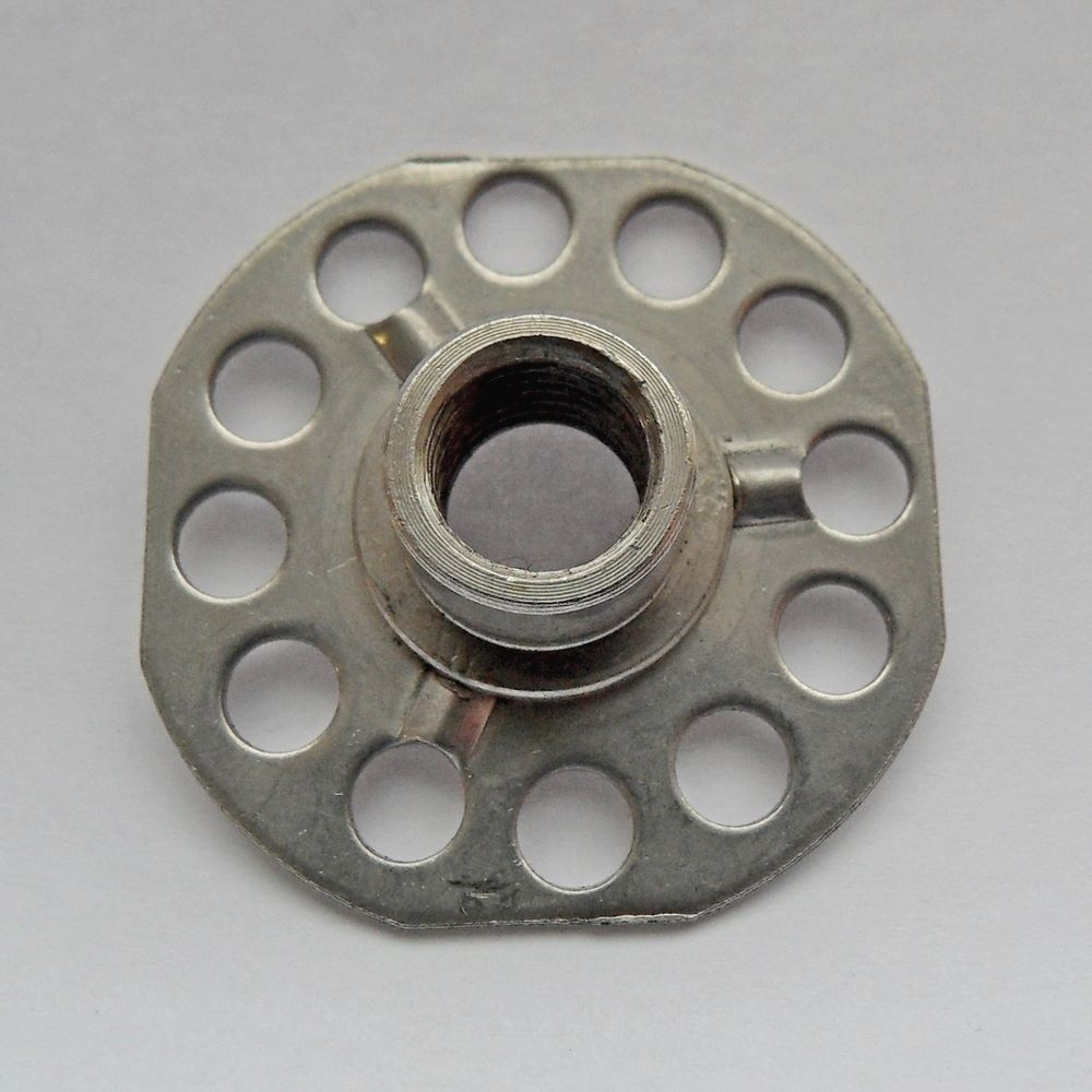
    In case of using thread insert i see 2 options normal thread insert (bigsert or keensert) or boding insert (see pic), Good point of using bonding insert is that insert base will be bonded to bulkhead and on the other side of insert i will have the bracket which will help to prevent insert un-bonding on pull out forces. However I do not know if tighting torque on this insert is similar to normal inserts.


    what material to use for the bracket ??, if made out of steel i believe will be cheaper as i think it can be done without machining, Also if finally stud is threaded into bracket this is the material to go.


    bottom bracket will come later...
    Attached Thumbnails Attached Thumbnails Click image for larger version. 

Name:	2019-11-20 20.11.56.jpg 
Views:	1238 
Size:	64.8 KB 
ID:	88917   Click image for larger version. 

Name:	bonding_insert.jpg 
Views:	1258 
Size:	98.9 KB 
ID:	88912  
    Last edited by rodorico83; 05.23.20 at 5:47 PM.

  2. #2
    Senior Member rodorico83's Avatar
    Join Date
    07.17.13
    Location
    Madrid, Spain
    Posts
    146
    Liked: 8

    Default

    mmm thread has been moved to historic, however this is not about a historic/vintage car...

  3. #3
    Senior Member
    Join Date
    01.11.05
    Location
    Zionsville, Indiana
    Posts
    3,172
    Liked: 1403

    Default

    What model of Lola is this chassis? Whatr was the original engine? It looks to me like ther mounts are designed to mate to castings that are bolted to the engine. Finally what engine are you going to install?

    I was an engineer on the Lola T97 and the Dallara chassis that were used in the Indy liights series. I may have some drawings/pictures of how those engines were installed..

  4. #4
    Senior Member rodorico83's Avatar
    Join Date
    07.17.13
    Location
    Madrid, Spain
    Posts
    146
    Liked: 8

    Default

    Quote Originally Posted by S Lathrop View Post
    What model of Lola is this chassis? Whatr was the original engine? It looks to me like ther mounts are designed to mate to castings that are bolted to the engine. Finally what engine are you going to install?

    I was an engineer on the Lola T97 and the Dallara chassis that were used in the Indy liights series. I may have some drawings/pictures of how those engines were installed..
    car is lola b99/50, original engine is the zytek and im installing the Solution F 3.5 (same as AER 3.5) used in renault world series, the first one is the mine one, (version used in STCC), i have to change cam covers for alloy ones with bore for studs at front and back, second is the single seater version.

    by the way i dunno t07 but t96 shares shames gearbox, and the car in which this engine installation has been done is a t96.


    this is engine gearbox sandwich plate

    Attached Thumbnails Attached Thumbnails Click image for larger version. 

Name:	2379610_orig.jpeg 
Views:	1211 
Size:	167.7 KB 
ID:	88926   Click image for larger version. 

Name:	3d-2.jpg 
Views:	1139 
Size:	18.6 KB 
ID:	88927  
    Last edited by rodorico83; 11.26.19 at 5:10 AM.

  5. #5
    Senior Member
    Join Date
    01.11.05
    Location
    Zionsville, Indiana
    Posts
    3,172
    Liked: 1403

    Default

    I think I understand what you have. The engine you want to use appears to be designed for a singm=le stud on eash bank of the engine and not shown is an oil pan that attaches along the bottom og the tub. I think I see an black bracket going across the bottom, just in front of the tube structure.

    I think I would stay with the single studs to mount the engine. The best reason I can think of is that the engine expands as it heats up and while this tub and engine structutre is very rigid, is does notve some and I think the single studs allow for that slight movement better that a super rigid bracket.

    I have done torsion tests on some composite tubs with stressed engines. They are very stiff but they do move under loads. I think that the single studs are used to allow some movement otherwise things ,ight start to crack or delaminate over time. This is just guessing on my part.

  6. #6
    Senior Member rodorico83's Avatar
    Join Date
    07.17.13
    Location
    Madrid, Spain
    Posts
    146
    Liked: 8

    Default

    Quote Originally Posted by S Lathrop View Post
    I think I understand what you have. The engine you want to use appears to be designed for a singm=le stud on eash bank of the engine and not shown is an oil pan that attaches along the bottom og the tub. I think I see an black bracket going across the bottom, just in front of the tube structure.
    Yes it is, as soon as i have the alloy cam cover
    Yes that bracket is the original bottom braket for the zytek (is made in alloy)

    Quote Originally Posted by S Lathrop View Post

    I think I would stay with the single studs to mount the engine. The best reason I can think of is that the engine expands as it heats up and while this tub and engine structutre is very rigid, is does notve some and I think the single studs allow for that slight movement better that a super rigid bracket.
    yes the famous engine expansion... we are talking of a couple of milimeters i guess ?

    Ok Single stud threaded into bracket or tube ??
    I guess you would reuse the older stud thread (for the zytek) to place a bolt there ??
    Would you keep the side extension of the bracket ?? I believe this is required if main stud is not inserted into the tube

    Quote Originally Posted by S Lathrop View Post
    I have done torsion tests on some composite tubs with stressed engines. They are very stiff but they do move under loads. I think that the single studs are used to allow some movement otherwise things ,tight start to crack or delaminate over time. This is just guessing on my part.
    Yes but if engine studs are fixed into bracket only, and bracket is tightly attached to the tube (with original stud thread, ~6 extra 1/4 bolts and side extension ) , that expansion will be handle only by those studs which i guess should be fine.


    what about this solution:

    bracket material steel
    stud threaded only into bracket
    bolt original stud thread in tube
    7 ~ 1/4 extra bolts to fix each bracket into tube (already 4 available)
    bracket with side extension to the tube sides, 2 extra 1/4 bolts to fix each bracket side into tube.

    for all extra 1/4 bolts a normal thread insert like keensert will be used.


    I think this is the cheaper easier, and actually quite similar to the T96 solution...

  7. #7
    Senior Member
    Join Date
    01.11.05
    Location
    Zionsville, Indiana
    Posts
    3,172
    Liked: 1403

    Default

    I would trust the designers of the tub as to how the engine should be mounted. the tub is not well suited to point loads. Look how large the brackets are that fasten to the tub. My bet it that there is a lot of structure inside the tub backing up those mounts.

  8. #8
    Senior Member rodorico83's Avatar
    Join Date
    07.17.13
    Location
    Madrid, Spain
    Posts
    146
    Liked: 8

    Default

    Some updates here.
    I have design already the bottom engine mount.


    Now working on the top brackets...
    As was mention before the plan is to fix the new bracket reusing all the tube threads of original bracket plus some new on the back of the tube around the new main stud axis and 2 on the tube side.
    Thread for main stud will be done in bracket ONLY, not on tube.
    Do you see you any constrain in this approach ?
    What is more suitable for the new inserts, keenserts type or this big head inserts ???
    Attached Thumbnails Attached Thumbnails Click image for larger version. 

Name:	bottom.png 
Views:	907 
Size:	54.9 KB 
ID:	92068  
    Last edited by rodorico83; 05.04.20 at 2:39 PM.

  9. #9
    Senior Member rodorico83's Avatar
    Join Date
    07.17.13
    Location
    Madrid, Spain
    Posts
    146
    Liked: 8

    Default

    Hello guys.
    more updates. I received the bottom engine mount in 7075 T6 material and the corresponding M12 studs.
    I should have design it a bit lighter it came a bit heavy i believe.
    Checked fitment and seems to be quite ok on tube and engine side
    As soon as I finish doing cam degree and finish head installation I will engage engine-tube and start designing the top bracket. I have some pre-designs already.
    I will post some pics later of bottom one.
    I will post also some pics of prototype for top brackets soon...


    Some insights on the best thread inserts for top mount ?
    where are those composite guys

  10. #10
    Senior Member rodorico83's Avatar
    Join Date
    07.17.13
    Location
    Madrid, Spain
    Posts
    146
    Liked: 8

    Default

    Updates.
    Bottom engine mount has been verified, and seems to be just fine.
    bolts alignment on tube side are perfe
    bolts alignment on engine side are perfect and centered.
    distance between engine and tube remains as original and floor and bodywork fits perfe.

    So engine side fixing is through 2 12.9 studs that inserts into the bracket around 55mm, first 25 threaded (more far from engine) and last 30 mm not threaded. mount thickness is about 20 mm on the engine side and 10 mm on the tube side. I reuse original steel shoulder washers for tube bolt fixing.


    TOP MOUNT
    As you can see in the pic the left top bracket main stud is at same level of the wiring tube bore, I was expecting this, thats why in the other installation i saw with this engine the studs where not threaded in tube.

    So i created a first version for the top mount, see attached.

    I was thinking to take advantage of that wiring bore in the tube and extend the bracket mating surface with an extra circular extrusion that goes into that wiring bore for about 8mm what do you think ? and in the other side that we dont have this issue, insert main stud into tube

    other option is to not insert into tube neither for right side
    I still have to place some extra holes in bracket for extra 1/4 bolts around the top main stud
    I will upload improved version soon...
    Attached Thumbnails Attached Thumbnails Click image for larger version. 

Name:	IMG_20200514_202922.jpg 
Views:	683 
Size:	39.6 KB 
ID:	92252   Click image for larger version. 

Name:	IMG_20200514_202944.jpg 
Views:	692 
Size:	47.2 KB 
ID:	92251   Click image for larger version. 

Name:	IMG_20200514_202953.jpg 
Views:	674 
Size:	42.3 KB 
ID:	92250  

    Click image for larger version. 

Name:	top_mount.PNG 
Views:	721 
Size:	124.0 KB 
ID:	92249  

  11. #11
    Senior Member rodorico83's Avatar
    Join Date
    07.17.13
    Location
    Madrid, Spain
    Posts
    146
    Liked: 8

    Default

    will appreciate some comments, so this does get too bored with just me posting...
    Last edited by rodorico83; 05.15.20 at 9:00 AM.

  12. #12
    Contributing Member
    Join Date
    01.17.17
    Location
    Derbyshire, United Kingdom
    Posts
    676
    Liked: 322

    Default

    Hi,

    As I understand;

    a) The Solution F (AER) is taller than the Zytek so the 'head' mountings on the chassis need to be higher than the position of the original mountings.

    b) Your 'new' mounting is a 1-part version of the 2-part (aluminium + steel) mounting.

    If the 2-part mounting worked correctly, then the 1-part version should work.

    Regarding fixing onto the chassis, I would keep to the same ones the 2-part mounting used. I can understand your idea to 'insert' into the wiring tube, but I don't think this would add much (any?) real strength to the part.

  13. #13
    Senior Member rodorico83's Avatar
    Join Date
    07.17.13
    Location
    Madrid, Spain
    Posts
    146
    Liked: 8

    Default

    Quote Originally Posted by tlracer View Post
    Hi,

    As I understand;

    a) The Solution F (AER) is taller than the Zytek so the 'head' mountings on the chassis need to be higher than the position of the original mountings.

    b) Your 'new' mounting is a 1-part version of the 2-part (aluminium + steel) mounting.

    If the 2-part mounting worked correctly, then the 1-part version should work.

    Regarding fixing onto the chassis, I would keep to the same ones the 2-part mounting used. I can understand your idea to 'insert' into the wiring tube, but I don't think this would add much (any?) real strength to the part.

    you understood well
    are you sure that will not add quite a bit of strength to the union for lateral forces ? is around 35 mm diameter extrusion of material inserted (obviously with no free play) into the chassis

    any suggestion about the type of carbonfiber inserts to use ??
    Last edited by rodorico83; 05.15.20 at 11:22 AM.

  14. #14
    Contributing Member
    Join Date
    01.17.17
    Location
    Derbyshire, United Kingdom
    Posts
    676
    Liked: 322

    Default

    Whether it will add significant lateral strength depends on if the wiring tube is designed to take a loading like that.

    I'm not an expert on composites but, from what have learned, the preferred option to an original, bonded-in at layup threaded insert is to use a 'big head' bonding insert fitted from the back of the panel.

  15. #15
    Senior Member rodorico83's Avatar
    Join Date
    07.17.13
    Location
    Madrid, Spain
    Posts
    146
    Liked: 8

    Default

    Well being the back side of the tube, all the back of monocoque is one of strongest parts of tube, and even better having a alloy tube that will help to spread the load around.

    big head on the back i see it difficult in this application. I dont know how deep is the backing, i would need to remove fuel tank...

  16. #16
    Contributing Member
    Join Date
    01.17.17
    Location
    Derbyshire, United Kingdom
    Posts
    676
    Liked: 322

    Default

    If you are drilling the chassis to add more mounting points, it would be sensible to remove the fuel tank anyway, to prevent damage.

    As well as the possibility to drill into the tank, it would be important to remove any debris from inside the cavity, as this could damage the tank also.

    How big is the tank access opening?

  17. #17
    Senior Member rodorico83's Avatar
    Join Date
    07.17.13
    Location
    Madrid, Spain
    Posts
    146
    Liked: 8

    Default

    Now i see the last part of your comment about that you will keep the 2part option. is that right ? why ? will not be simpler & stronger have a one part mount ?


    Quote Originally Posted by tlracer View Post
    Hi,


    Regarding fixing onto the chassis, I would keep to the same ones the 2-part mounting used. I can understand your idea to 'insert' into the wiring tube, but I don't think this would add much (any?) real strength to the part.

  18. #18
    Senior Member rodorico83's Avatar
    Join Date
    07.17.13
    Location
    Madrid, Spain
    Posts
    146
    Liked: 8

    Default

    Quote Originally Posted by tlracer View Post
    If you are drilling the chassis to add more mounting points, it would be sensible to remove the fuel tank anyway, to prevent damage.

    As well as the possibility to drill into the tank, it would be important to remove any debris from inside the cavity, as this could damage the tank also.

    How big is the tank access opening?
    I was checking the wiring tube closely and is like bore and tube are not the same diameter as i can see kind of adhesive material in the edge between bore and tube so i guess there was some clearance, as i don´t think that clearance has been fully and properly filled with structural adhesive i will not use this feature

    im pretty sure tank is at least 6 cm away from backside all the way around the tube. I dont think there is such risk as i will not drill more than 1inch neither on the back nor on the side.

    See this interesting pic of left side, you can see a steel plate which is the one that holds the main stud, so no bighead was used i think and a plate was instead so a better load spread. (in red square)


    This from f1 car, I dont know if that plate on the back is for manufacturing purposes or it really goes in the car...


    Here moreless what will be the final solution

    For all new inserts i will use keenserts being the most successful ones in pulling forces based on some studies i read, i have them if any wants them.
    thread 1/4 UNC as the current ones
    I will reuse all the available threads including the ones of the floor tensioner mounts
    I changed my mind, i still have to check machining prices, but material will be carbon steel so thread stud is on steel instead of alloy and the better strength in the side 90º corner of each plate.
    i will check the possibility to have it in one part otherwise i will make 2 parts: side plate and front mount then weld both on the edge.

    For the moment seems that i do not have properly aligned the top part of tube with engine as i can not align symmetric brackets (the studs bores) and there is some offset of no more than a 1mm.
    I have already engine and tube parallel so I know the exact length for the studs threads in the brackets.


    I also have design ready for an aux plate between gearbox and engine that will hold engine head studs


    Attached Thumbnails Attached Thumbnails Click image for larger version. 

Name:	Capture2.JPG 
Views:	514 
Size:	36.0 KB 
ID:	92329   Click image for larger version. 

Name:	IMG_20200522_200521.jpg 
Views:	544 
Size:	58.5 KB 
ID:	92333   Click image for larger version. 

Name:	IMG_20200523_211237.jpg 
Views:	493 
Size:	38.5 KB 
ID:	92331  

    Click image for larger version. 

Name:	Capture3.JPG 
Views:	512 
Size:	43.6 KB 
ID:	92332   Click image for larger version. 

Name:	2.jpg 
Views:	500 
Size:	42.7 KB 
ID:	92330   Click image for larger version. 

Name:	IMG_20200521_191135.jpg 
Views:	513 
Size:	58.6 KB 
ID:	92328  

    Last edited by rodorico83; 05.23.20 at 6:02 PM.

  19. #19
    Contributing Member
    Join Date
    01.17.17
    Location
    Derbyshire, United Kingdom
    Posts
    676
    Liked: 322

    Default

    Quote Originally Posted by rodorico83 View Post
    Now i see the last part of your comment about that you will keep the 2part option. is that right ? why ? will not be simpler & stronger have a one part mount ?
    The one piece mount would be better than two piece. What I meant was that I see no big benefit to having the mount extend into the wiring tube. While it adds a little to lateral location, it will not help the mount from pulling out.

    The steel part you show in the first picture looks like it was bonded into the structure when it was first built, to spread load from the stud.

    In the 'F1 car' picture, the big plate is the jig to align the top and bottom parts of the chassis before bonding them together. The jig has a big 6-sided hole in it, presumably to give access to inside the fuel tank cavity during construction.

    Also, back to the question I asked earlier - how big is the fuel tank access on your chassis? And where is it?
    Last edited by tlracer; 05.25.20 at 3:07 AM.

  20. #20
    Senior Member rodorico83's Avatar
    Join Date
    07.17.13
    Location
    Madrid, Spain
    Posts
    146
    Liked: 8

    Default

    Quote Originally Posted by tlracer View Post
    The one piece mount would be better than two piece. What I meant was that I see no big benefit to having the mount extend into the wiring tube. While it adds a little to lateral location, it will not help the mount from pulling out.

    The steel part you show in the first picture looks like it was bonded into the structure when it was first built, to spread load from the stud.

    In the 'F1 car' picture, the big plate is the jig to align the top and bottom parts of the chassis before bonding them together. The jig has a big 6-sided hole in it, presumably to give access to inside the fuel tank cavity during construction.

    Also, back to the question I asked earlier - how big is the fuel tank access on your chassis? And where is it?
    opening is in cockpit behind seat see pic.
    Attached Thumbnails Attached Thumbnails Click image for larger version. 

Name:	Capture.JPG 
Views:	510 
Size:	61.2 KB 
ID:	92361  

  21. #21
    Senior Member rodorico83's Avatar
    Join Date
    07.17.13
    Location
    Madrid, Spain
    Posts
    146
    Liked: 8

    Default

    I finally got the correct alignment between engine and the top of the tube with symmetric mounts.
    Im in talks with guy in UK, which I think he was a lola worker in the composites department, he might manufacture for me the inserts.
    I came back to him (we talk quite time ago when i was starting the project) cos i saw that there is no long version for the keensert

  22. #22
    Contributing Member
    Join Date
    01.17.17
    Location
    Derbyshire, United Kingdom
    Posts
    676
    Liked: 322

    Default

    I am still concerned about the idea of putting additional threaded inserts into what appears to be a carbon/honeycomb structure, so I hope the person you are talking with has the necessary expertise to do this.

    From my understanding of your requirement, the inserts will need to have some way to prevent 'pull through'. This needs a bobbin-type insert, so something with fairly large diameter flanges to spread the load.

    As I said much earlier, these would be inserted during construction, normally, and not afterwards. The only way I can see to insert after build is using something like a 'big head', fitted and preferably bonded on from inside the tank cavity. Hence why I asked about the access hatchway.

    Otherwise - depending on the height difference between the original mounting points and the front studs on your intended engine - I would have thought a machined adapter block would have been a more logical solution. If you look how the T96/50 was fitted with a Chrysler engine for the Mexican F3000 series, you will see what I mean (link below):

    https://cdn.bringatrailer.com/wp-con...da100_1657.jpg

  23. #23
    Senior Member rodorico83's Avatar
    Join Date
    07.17.13
    Location
    Madrid, Spain
    Posts
    146
    Liked: 8

    Default

    Hi,
    these cars are full of kennserts around the tube in cockpit and in the exterior.
    The car has already even some new keenserts in the back of the tube.
    This is quite common but of course several things has to be taken into account before doing it ...
    thats why keenserts are used that normally external thread are 2 sizes higher than internal.
    Of course all these high extress mounts are installed during manufacturing but that is not the case in this application...
    so dont loose time thinking on that...


    that t96 is the one of Charles ?
    that engine come with no stud originally right ? and see those 3 bolts on top of the head.
    You have also to consider the engine design to do that and i dont think mine is suitable, due to the lack of extra points to fix that adaptor around that area....
    But actually i never though on this type of solution, but look simpler


    Quote Originally Posted by tlracer View Post
    I am still concerned about the idea of putting additional threaded inserts into what appears to be a carbon/honeycomb structure, so I hope the person you are talking with has the necessary expertise to do this.

    From my understanding of your requirement, the inserts will need to have some way to prevent 'pull through'. This needs a bobbin-type insert, so something with fairly large diameter flanges to spread the load.

    As I said much earlier, these would be inserted during construction, normally, and not afterwards. The only way I can see to insert after build is using something like a 'big head', fitted and preferably bonded on from inside the tank cavity. Hence why I asked about the access hatchway.

    Otherwise - depending on the height difference between the original mounting points and the front studs on your intended engine - I would have thought a machined adapter block would have been a more logical solution. If you look how the T96/50 was fitted with a Chrysler engine for the Mexican F3000 series, you will see what I mean (link below):

    https://cdn.bringatrailer.com/wp-con...da100_1657.jpg

  24. #24
    Contributing Member
    Join Date
    01.17.17
    Location
    Derbyshire, United Kingdom
    Posts
    676
    Liked: 322

    Default

    Quote Originally Posted by rodorico83 View Post
    that engine come with no stud originally right ? and see those 3 bolts on top of the head.
    You have also to consider the engine design to do that and i dont think mine is suitable, due to the lack of extra points to fix that adaptor around that area....
    Your engine has much of that work done already with the extended cam covers and mounting studs, it doesn't need any extra fixing points.

    Quote Originally Posted by rodorico83 View Post
    But actually i never though on this type of solution, but look simpler
    Yes, simply a machined aluminium block that locates on the 4 existing chassis points and extends upward to meet the engine stud. No chassis modifications needed!

  25. #25
    Senior Member rodorico83's Avatar
    Join Date
    07.17.13
    Location
    Madrid, Spain
    Posts
    146
    Liked: 8

    Default

    Quote Originally Posted by tlracer View Post
    Your engine has much of that work done already with the extended cam covers and mounting studs, it doesn't need any extra fixing points.


    Yes, simply a machined aluminium block that locates on the 4 existing chassis points and extends upward to meet the engine stud. No chassis modifications needed!
    I do not think is possible to just use the original 4 bolts and main stud, the new studs is far away up. it will leave all the load to the bottom of the bracket and being so far from new stud, i dont know i dont think that will properly hold, even worse on pulling as there is nothing on that area of the bracket that fixes it to the tube

    At the end and adaptor & bracket together is what im doing but adding some more points on top of the bracket around new stud and on the side.
    Last edited by rodorico83; 05.26.20 at 12:29 PM.

  26. #26
    Contributing Member
    Join Date
    01.17.17
    Location
    Derbyshire, United Kingdom
    Posts
    676
    Liked: 322

    Default

    I am simply concerned you will be feeding loads into the monocoque where it wasn't designed to take them, using fastenings that may or may not be suitable.

    Clearly you are happy with your own ideas, so I'll let you continue with them. Good luck with the conversion.

  27. #27
    Senior Member rodorico83's Avatar
    Join Date
    07.17.13
    Location
    Madrid, Spain
    Posts
    146
    Liked: 8

    Default

    Quote Originally Posted by tlracer View Post
    I am simply concerned you will be feeding loads into the monocoque where it wasn't designed to take them, using fastenings that may or may not be suitable.

    Clearly you are happy with your own ideas, so I'll let you continue with them. Good luck with the conversion.
    Thanks.
    This is a proven solution from a winning car that i know will work
    There is no way to place this engine using only the head studs with no adding more fixing points into the tube, as the new head stud is quite far away from original, and just reusing the original points will put too much stress on them than what is expected to be.
    Solution of placing bigheads from fuel tank cavity is too complex and will cost a lot more than this one, but i reckon that might be the best
    About fasteners well I did my research on this...
    Last edited by rodorico83; 05.27.20 at 3:49 PM.

  28. #28
    Senior Member rodorico83's Avatar
    Join Date
    07.17.13
    Location
    Madrid, Spain
    Posts
    146
    Liked: 8

    Default

    Has been some time i dont post updates here.
    I finished with this time ago, so lets show some result here
    Due to the thickness and design of the back panel, the final solution has been 38mm base big head inserts. insert lenght 20mm for M6 and 25 for M8 side ones, bonding resin Loctite EA 9466 in the base of the insert to fix position with engine mounts installed and as second step injected in the back panel to fix the insert collar.
    first 6mm of thread in inserts were removed to admit bolt with some grip part
    Surprisingly was even possible to carefully install them with the fuel bladder in.
    So configuration, new 3 M6 inserts has been placed in the back of the tube and and M8 on the side. a bit tricky with the right side due to the proximity with the alloy loom tube. This plus the 4 original and main bolt.
    Engine mount mid carbon steel 1045, 2 part, side and back and welded together.
    Some pics of the back of inserts attached. i will post soon of front view.
    link with small video of project status after finally marry gearbox clutch and engine, you will have to download to watch
    https://drive.google.com/file/d/187o...ew?usp=sharing


    Attached Thumbnails Attached Thumbnails Click image for larger version. 

Name:	1607448163470.jpg 
Views:	291 
Size:	92.7 KB 
ID:	95309   Click image for larger version. 

Name:	1607448163466.jpg 
Views:	307 
Size:	106.3 KB 
ID:	95310  

Thread Information

Users Browsing this Thread

There are currently 1 users browsing this thread. (0 members and 1 guests)

Posting Permissions

  • You may not post new threads
  • You may not post replies
  • You may not post attachments
  • You may not edit your posts
  •  


About Us
Since 2000, ApexSpeed.com has been the go-to place for amateur road racing enthusiasts, bringing together a friendly community of racers, fans, and industry professionals. We're all about creating a space where people can connect, share knowledge, and exchange parts and vehicles, with a focus on specific race cars, classes, series, and events. Our community includes all major purpose-built road racing classes, like the Sports Car Club of America (SCCA) and various pro series across North America and beyond. At ApexSpeed, we're passionate about amateur motorsports and are dedicated to helping our community have fun and grow while creating lasting memories on and off the track.
Social