Results 1 to 39 of 39
  1. #1
    Global Moderator carnut169's Avatar
    Join Date
    01.22.02
    Location
    Atlanta, Ga
    Posts
    3,700
    Liked: 11

    Default Belly pan add stiffness?

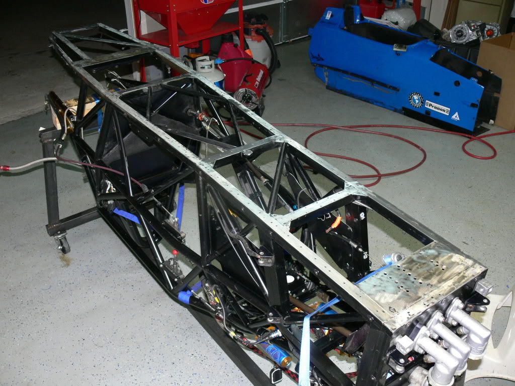
    Some friends came over last night and amoung other things we inverted the Mygale and removed the bellypan.

    Two of the guys there are engineers who work (or worked) at Dobbins- aircraft guys. They pretty much insisted that the belly pan is a dust cover and adds no stiffness to the frame. They've both seen Van Diemens, Reynards and said the Mygale frame looks stronger- that the amount of support the stressed pan will provide largly depends on the strength of the frame to begin with (which does make sense) and since my frame is so nicely done the bellypan is doing nothing.

    Everything I've read here says the opposite- a properly bonded bellypan does add considerable stiffness.

    So which is it?
    Sean O'Connell
    1996 RF96 FC
    1996 RF96 FB
    2004 Mygale SJ04 Zetec

  2. #2
    Contributing Member Tom Valet's Avatar
    Join Date
    11.18.05
    Location
    New York
    Posts
    1,613
    Liked: 157

    Default

    Sean, this is not scientific, purely anecdotal, but after Bill's crash in qualifying at the Watkins Glen race in June the car gradually became more and more undriveable, to the point that by the end of the Mid-Ohio races he could barely keep it on the road. The car was torn down and they found that a portion of the belly pan had separated at the rear of the frame, causing the frame to flex under load. The entire pan was removed and rebonded/rivited and after that the car was back to its former self.

    Granted, this is a frame that is now 20+ years old, so maybe that has some effect on the issue, but in our case the pan itself appears to play a significant role in maintaining frame stiffness.

    Maybe the newer frame designs dont rely on the pan as much and/or the newer frames themselves are still retaining stiffness and as they get older they begin to flex and the pan becomes more important.

  3. #3
    Contributing Member DaveW's Avatar
    Join Date
    06.25.01
    Location
    Bath, OH
    Posts
    6,187
    Liked: 3315

    Default

    Unless the bottom of the car is fully triangulated, similar to most of the rest of the frame, the belly pan IS the triangulation. Without triangulation, tubes are in bending, and stiffness will go way down.
    Dave Weitzenhof

  4. #4
    Contributing Member TimW's Avatar
    Join Date
    01.30.03
    Location
    Santa Cruz, CA
    Posts
    2,570
    Liked: 23

    Default

    Quote Originally Posted by carnut169 View Post

    Everything I've read here says the opposite- a properly bonded bellypan does add considerable stiffness.

    So which is it?
    Should it matter? It certainly won't reduce stiffness, you have to have a pan, and its a good place for ballast. The work to install and remove a bonded pan is trivial compared to drilling the 200 some odd 1/8 holes (especially if stainless). And rivet heads get scrapped off over kerbing...

    And, now with 7 months at working at a _very_ data driven company: twist it and see by comparing the measurements.
    ------------------
    'Stay Hungry'
    JK 1964-1996 #25

  5. #5
    Senior Member Tom Sprecher's Avatar
    Join Date
    01.29.02
    Location
    Living race car free
    Posts
    830
    Liked: 0

    Default

    From what I could see and remember from last night the bottom plane of the frame is fully triangulated, unlike many of the older chassis I have seen.

    This is why a couple of us questioned the actual added rigidity of the belly pan. We felt its primary function was to keep rocks and other track debris away from your tender parts.
    Tom Sprecher
    ATL Region Treasurer

  6. #6
    Contributing Member RussMcB's Avatar
    Join Date
    03.19.02
    Location
    Palm Coast, FL
    Posts
    6,681
    Liked: 553

    Default

    Question: Since a belly pan is 2 dimensional, does that mean it only helps prevent twisting in that one plane/axis?

    Hope that makes sense. I can picture what I'm asking. Not sure about the best words.

    Try #2: Does a belly pan prevent, say, the Left Front tire from becoming closer or farther away from the Left Rear tire?

    It seems like that is the only type of twisting it can prevent.

    PS. Sean's Mygale is pretty well triangulated on the floor, except for a square section under the fuel cell.
    Racer Russ
    Palm Coast, FL

  7. #7
    Contributing Member Roux's Avatar
    Join Date
    09.07.02
    Location
    Connecticut
    Posts
    1,318
    Liked: 157

    Default Huge differnce

    For my Masters Degree final project I measured the RP31 before and after adding some tubes and bonding on an aluminum 0.063" belly pan. The pan was on with only rivets before and was fully glued and rivetted after. Also made FEA models. Actual measurement (done with strict review and criticism) ended up more than double the torsional stiffness and even higher than the FEA had predicted.

    To educate your engineer friends have them do this mind excercise. the torsion axis of interest is somewhere in the middle of the car runnng fore and aft. It is well known that if you want to make something stiff while light in tosion you put all of the metal as far away from the axis as possible. think gun drilled half shafts. The stuff in the center does nearly nothing. Adding a shear panel parallel to the axis and at a substantial distance away makes a HUGE difference if of course it is attached correctly. If your buddies don't get it then I challenge them to teach me what I missed. Even if you have a honecomb structure you must box it in as far from the neutral axis with a skin if you want to optimize for stiffness

  8. #8
    Senior Member Tom Sprecher's Avatar
    Join Date
    01.29.02
    Location
    Living race car free
    Posts
    830
    Liked: 0

    Default

    Quote Originally Posted by Roux View Post
    I measured the RP31 before and after adding some tubes and bonding on an aluminum 0.063" belly pan.
    What did the bottom plane of the frame look like? Was it triangulated? What are the tubes you refer to and where were they placed?

    The tubing on the largest section of the bottom plane of the Mygale frame resembles a rectangle with a diamond inside.

    We were not advocating the belly pan is not necessary, instead we felt it does not add as much stiffness as on other chassis.


    Quote Originally Posted by RussMcB View Post
    Question: Since a belly pan is 2 dimensional, does that mean it only helps prevent twisting in that one plane/axis?
    Yes. Look at it this way. If the bottom plane of the frame is a rectangle, the bonded pan prevents it from being twisted into a parallelogram. You can try it with a sheet of aluminum. Easy to bend in half, but close to impossible to twist into a parallelogram.
    Tom Sprecher
    ATL Region Treasurer

  9. #9
    Contributing Member RussMcB's Avatar
    Join Date
    03.19.02
    Location
    Palm Coast, FL
    Posts
    6,681
    Liked: 553

    Default

    Steve, can you describe (in layman's terms) how you measured the stiffness? For instance, did you secure one end of the car then (on the other end) hang weight on a lever and measure how far it moved for each xx lbs. added?

    Just trying to visual the forces. Thanks.
    Racer Russ
    Palm Coast, FL

  10. #10
    Senior Member
    Join Date
    01.11.05
    Location
    Zionsville, Indiana
    Posts
    3,172
    Liked: 1403

    Default

    You may have the evidence for what you can expect from a properly installed belly pan. If the belly pan you removed had any loose or broken rivets and/or showed any signs of fretting against the bottom of the frame, then you need to install a belly pan that is fully riveted and bonded.

    We have seen a significant improvement when we added 1" wide strips to the bottom frame rails so we have a 2" wide area for bonding and riveting. We use solid rivets any place we can. Belly pans now last 5 years. And we use .083 aluminum vs. .065.

    Attaching the belly pan as I do on the Citations is a lot of work. But in our testing it increased the torsional regidity of our cars close to 20%. That was way easier than any other thing I could do to get that improvement. It also saved a lot of labor by not having to replace the belly pan every year or so.

  11. #11
    Global Moderator carnut169's Avatar
    Join Date
    01.22.02
    Location
    Atlanta, Ga
    Posts
    3,700
    Liked: 11

    Default

    Interesting. I'll attach a photo of the chassis later but feel there has to be some effect...

    The car came with a thin aluminum pan riveted (with steel rivets?) and probably bonded to the chassis. Then, a layer of jabrock covered the entire floor.

    I am replacing the thin pan with one thats .083" (no jabrock) and I will have it anodised prior to bonding. The aircraft guys mentioned above said they'll help me get the right 3/16" rivets, counter sink (with stop)/ clekos, markers, etc. I've done this a few times now and it's not a bad job (IMHO).

    Time will tell if the car feels any different but there was nothing that held the pan on with the rivets removed and most of them spun in the holes- in places the rivets pulled through the pan.
    Sean O'Connell
    1996 RF96 FC
    1996 RF96 FB
    2004 Mygale SJ04 Zetec

  12. #12
    Senior Member
    Join Date
    12.22.04
    Location
    Knoxville,Tn
    Posts
    519
    Liked: 65

    Default

    @ Russ. I have a copy of Steve's paper (I have an RP31 hmmm, THANKS STEVE!!) and yes, thats pretty much how he did it and also how a few other chassis folk have told me to measure the stiffness. Use solid bars or rods as shocks. Lock down one end to ground or jig and then use rigid beam connected to both hubs parallel to axle. add weigh, measure the chassis twist.

    @ Sean These engineers, what aircraft do they work on? have had input into design of? I do not want to fly on those aircraft if they don't understand the concept of stressed skin. I was in school for aerospace eng years ago, life happened and now work at Oak Ridge National Labs. I have seen engineers overlook many things.

  13. #13
    Senior Member
    Join Date
    08.18.02
    Location
    Indy, IN
    Posts
    6,288
    Liked: 1880

    Default

    Yes, the pan will add torsional stiffness to the frame even if the bottom is fully triangulated - just think of it as more material that has to be stretched whenever the frame is trying to twist. Granted, the percentage increase won't be as much as if the pan were added to an untriangulated frame base, but it will still be significant.


    Tell your engineer friends to go back and review their old college texts!

    The work to install and remove a bonded pan is trivial compared to drilling the 200 some odd 1/8 holes (especially if stainless)
    Those same rivits are still there on a properly bonded pan - they are needed to clamp the pan correctly as the epoxy hardens.

    To measure the frame rigidity is not that hard. Do a search - a full procedure was posted some time back.

  14. #14
    Senior Member
    Join Date
    08.18.02
    Location
    Indy, IN
    Posts
    6,288
    Liked: 1880

    Default

    Quote Originally Posted by carnut169 View Post
    Time will tell if the car feels any different but there was nothing that held the pan on with the rivets removed and most of them spun in the holes- in places the rivets pulled through the pan.
    The fact that the rivets were loose will tell you that they were being stressed. If you did nothing more than just replace them and go back to the track, you would feel the benefit for a while ( the car would either go slightly loose or maybe just show less push, depending on the original balance), but would quickly deteriorate as the rivets loosened up again.

  15. #15
    Heterochromic Papillae starkejt's Avatar
    Join Date
    07.04.07
    Location
    VA
    Posts
    2,540
    Liked: 3

    Default

    I came here to dispute the opinions of the engineers in the OP, but I see the brain trust has already taken care of it.

  16. #16
    Senior Member Neil_Roberts's Avatar
    Join Date
    03.08.11
    Location
    SoCal
    Posts
    618
    Liked: 102

    Default

    There is an easy way to measure whether or not your frame is getting softer as it gets older, assuming you have a set of wheel scales. Just install your reference set of springs, or solid struts, and measure how much the crossweight changes after adding a 1/4" thick shim under your left front tire.

    Measure it now, then again every few races. Ideally, you will get the same result every time. If the crossweight is less than last time, it's time to find out why.

    There is a description of how to make your own dirt-cheap setup pad in Chapter 15 of Think Fast. Also, there is a description of my favorite torsional stiffness test method in there.

  17. #17
    Contributing Member Roux's Avatar
    Join Date
    09.07.02
    Location
    Connecticut
    Posts
    1,318
    Liked: 157

    Default Measuring twist

    Russ and others,

    I set up the front of the car with a jack stand under the left front of the frame at the front bulkhead. Then on the right side at that bulkhead I ran a beam up to the ceiling making sure it was preloaded and quite rigid. Even then , as you add torque to the rear (back of the engine bulkhead) you get some compression of the beam and hence rotation of the front reference. This means that you need to measure the rotation of the front and the rear and subtract them to get the actual amount of chassis twist. At the back in the middle of the rear bulkhead I used a piece of angle iron between the bottom and the floor as a sharp pivot point. Not sure if that is clear, but you need to constraint the rear of the car only vertically. You want no rotational constraint. I then attached a long 2x8 to the rear of the car going out latterally to the left side and ran it under the table of the bridegeport milling machine. It was clamped with C clamps to the chassis. something simple is fine. I was able to add torque by lowering the milling table with the hand crank. the beam was quite flexible but it doesn't matter since torque is force times distance. The torque was measered with a corner scale between the wood beam and the bridgeport. I made sure that the scale was being pressed directly in the middle with another angle iron pivot, probably between two pieces of wood. As you add weight (lowering the table) you don't want the effective length of the torqueing arm to change since you calculate torque by multiplying that length by the weight read out from the scale. The royale has the long rear cross beam that goes way out towards the wheels on each side and I then set up dial indicators to measure height changes on both ends of the beam. Knowing the distance between the indicators you can calculate the rotation of the rear. I used a rediculouly precise mitutoyo level to get the rotation of the front reference bulkhead. I added torque in uniform increments at the back and found the data to be linear and with less noise than I expected. The surfaces where the dial indicators read are somewhat rough and gave some small error.

    I have to find the paper and look at it to see if I would be mortally embarrassed to post it. I was still on a steep learning curve and feel like I probably mucked up some of it!

    The RP31 is not well triangulated on the bottom and is therfore ripe for improvement. I can understand that a car with good triangulation will gain less, but a shear plate that is well attached is always going to add substantial benefit.

    If there was no force between a bonded pan and the frame then why would any of them ever loosen up?
    Last edited by Roux; 12.03.11 at 2:26 AM.

  18. #18
    Senior Member
    Join Date
    01.11.05
    Location
    Zionsville, Indiana
    Posts
    3,172
    Liked: 1403

    Default

    Roux:

    I use a much simpler system that was developed years ago to measure the condition of aluminum monocoques. It is essentially the same process that you describe but I am using the complete car to do the test.

    Replace the shocks with struts. Mount the rear of the car on set of rims (no tires) and block the car up a foot or more. I use an angle iron pivot at the front, as you describe. I have made my pivot so that it is at the front roll center. I have a beam that attaches to the front upright and extends 6 ft. from the center line of the car. I have the beam so that I can place a 50 lb weight 5 and 6 ft from the center of the car.

    To take the measurements, I place 4 dial indicators 32" form the center of the car, one at each bulkhead (front, dash, roll bar, and rear). The bars are only clamped to the far side of the frame. This system gives the displacement at each bulkhead as the car is loaded. 50 lbs load at 6 Ft. equals 300 ft/lbs. 300 lbs is about the weight on a rear corner and you are loading the rear corner on the loaded side of the car as it is in service. You want to be careful when you load the car because you can bend it this way.

    This system can be setup and run in a few hours once the equipment is acquired or built. When I have encountered a car that we have had trouble getting to work properly, I go to this system. I used this system on the Swift 08 and the early Stohr DSR. I can tell you that what people were saying about the cars were not the issues I found. The Swift had a bell housing that was way worse than the tub. That part was replaced during the first season. The Stohr was not as bad as every one thought, in fact it was acceptable as it was.

  19. #19
    Global Moderator carnut169's Avatar
    Join Date
    01.22.02
    Location
    Atlanta, Ga
    Posts
    3,700
    Liked: 11

    Default

    Here is the inverted Mygale frame...

    Sean O'Connell
    1996 RF96 FC
    1996 RF96 FB
    2004 Mygale SJ04 Zetec

  20. #20
    Senior Member
    Join Date
    01.11.05
    Location
    Zionsville, Indiana
    Posts
    3,172
    Liked: 1403

    Default

    Sean;

    It appears that there is no diagonal bracing under fuel cell or the foot box. Thus in those areas the belly pan will be necessary. The corner gussets are added to improve the attachment of the belly pan to the frame.

    One simple improvement would be to 5/32 rivets spaced 1" or less and staggered 1/4" either side of the center of each tube. This will be way better than 3/16 rivets going down the center. And use solid rivets any place you can get a bucking bar behind the rivet. You absolutely must glue and rivet. I like 5/32 rivets because they are strong enough by themselves to do the job and you can get over sized 5/32 rivets if you have a hole that is too large. Finally you have the opting of replacing one with a 3/16 as a field repair if necessary.

    The next level of improvement would be to add a 1" strip to the inside edge of the bottom rails for increased rivet and bonding area. And using ,o83 aluminum will give a nice improvement over .065.

    When you bond the belly pan to the lower frame rails, you in effect make the bonded tubes and the belly pan into a single structure that is much stronger than either of the 2 structures individually. The lower tubes themselves are now stronger simply because one wall is now .140 to .160 thick.

  21. #21
    Fallen Friend Swift17's Avatar
    Join Date
    12.05.05
    Location
    Plantation, Florida
    Posts
    1,185
    Liked: 232

    Default .... and, ?

    OK, the db-1 needed and installed -- full length and cross frame the 1" steel surfaces, (some diagonal/45s bracing next to the fuel cell too), anodized flat ally pan sized (built in "tabs" for the front of the lower engine body panels/covers), cut and drilled (300+ countersunk cuts made as well -loved the adjustable depth aircraft countersink tool), bonding stuff mixed, clamped and then rivets installed (May, 2009 -and appears still as tight as a Ritz-Carlton suite sheet); can we move the discussion to:

    concept of/necessity for the installation of a Jabroc floor, with suggestions for total length, thicknesses, method(s) of attachment, effect on ride height - advisability of it being sectioned, with front/footbox area removable for serviceability/replacement ?

    [Sean specs/pics of yours as originally installed and current plan ...... ? ]

    EJ

  22. #22
    Global Moderator carnut169's Avatar
    Join Date
    01.22.02
    Location
    Atlanta, Ga
    Posts
    3,700
    Liked: 11

    Default

    Quote Originally Posted by S Lathrop View Post
    Sean;

    It appears that there is no diagonal bracing under fuel cell or the foot box. Thus in those areas the belly pan will be necessary. The corner gussets are added to improve the attachment of the belly pan to the frame.

    One simple improvement would be to 5/32 rivets spaced 1" or less and staggered 1/4" either side of the center of each tube. This will be way better than 3/16 rivets going down the center. And use solid rivets any place you can get a bucking bar behind the rivet. You absolutely must glue and rivet. I like 5/32 rivets because they are strong enough by themselves to do the job and you can get over sized 5/32 rivets if you have a hole that is too large. Finally you have the opting of replacing one with a 3/16 as a field repair if necessary.

    The next level of improvement would be to add a 1" strip to the inside edge of the bottom rails for increased rivet and bonding area. And using ,o83 aluminum will give a nice improvement over .065.

    When you bond the belly pan to the lower frame rails, you in effect make the bonded tubes and the belly pan into a single structure that is much stronger than either of the 2 structures individually. The lower tubes themselves are now stronger simply because one wall is now .140 to .160 thick.

    Thanks.
    Would you advise drilling new 5/32" holes or using the existing 5/32" holes? The existing holes are down the center as you can see. I could add the 1" strip in a few places but not in the fuel cell area, and the footbox has that steel plate covering the pedal area so marginal gain?
    Sean O'Connell
    1996 RF96 FC
    1996 RF96 FB
    2004 Mygale SJ04 Zetec

  23. #23
    Global Moderator carnut169's Avatar
    Join Date
    01.22.02
    Location
    Atlanta, Ga
    Posts
    3,700
    Liked: 11

    Default

    Quote Originally Posted by Swift17 View Post
    [Sean specs/pics of yours as originally installed and current plan ...... ? ]

    EJ

    Don't really have any photos of the floor prior to removing it, but in this pic you can see the jabrock under the aluminum.

    I will be replacing the pan with .083 6061 (anodised), counter sunk rivets (cherrymax?), and bonded with Hysol.

    Sean O'Connell
    1996 RF96 FC
    1996 RF96 FB
    2004 Mygale SJ04 Zetec

  24. #24
    Fallen Friend Swift17's Avatar
    Join Date
    12.05.05
    Location
    Plantation, Florida
    Posts
    1,185
    Liked: 232

    Default .... and, ?

    SteveL & DaveW

    .... concept of/necessity for the installation of a Jabroc floor, with suggestions for total length, thicknesses, method(s) of attachment, effect on ride height - advisability of it being sectioned, with front/footbox area removable for serviceability/replacement ?

    EJ
    Last edited by Swift17; 12.05.11 at 3:45 AM.

  25. #25
    Member
    Join Date
    04.01.11
    Location
    milwaukee wi
    Posts
    15
    Liked: 0

    Default

    I'll add my $0.02. The diamond bracing under the cockpit had to have been designed with the belly pan used as a stressed member. Without the pan the frame is not properly triangulated.

  26. #26
    Senior Member
    Join Date
    01.11.05
    Location
    Zionsville, Indiana
    Posts
    3,172
    Liked: 1403

    Default

    Quote Originally Posted by carnut169 View Post
    Thanks.
    Would you advise drilling new 5/32" holes or using the existing 5/32" holes? The existing holes are down the center as you can see. I could add the 1" strip in a few places but not in the fuel cell area, and the footbox has that steel plate covering the pedal area so marginal gain?
    Having the extra holes will not be an issue. A single row of rivets works like a hinge axis. I do 4 rows of rivets on the bottom of all my frame rails.

  27. #27
    Senior Member ghickman's Avatar
    Join Date
    04.20.07
    Location
    Alpine California
    Posts
    1,192
    Liked: 273

    Default Welded steel belly pans

    If you can stand the weight penalty I've always prefered welded steel belly pans. Last far longer with no rivets to shake loose and the weight is down low. They're far less prone to damage during off track mishaps.
    Gary Hickman
    Edge Engineering Inc
    FB #76

  28. #28
    Contributing Member
    Join Date
    12.10.02
    Location
    New Jersey
    Posts
    1,092
    Liked: 20

    Default

    I plan on a welded or brazed pan for my RF78. Unless there's a compelling reason not to, I was going to use stainless, so I don't have to paint it.

  29. #29
    Senior Member
    Join Date
    01.11.05
    Location
    Zionsville, Indiana
    Posts
    3,172
    Liked: 1403

    Default

    Gary makes a good argument for welding belly pans on.

    Damage a welded belly pan and what do you do?

    I have done a lot of cars with welded belly pans. And they proved to be a problem when it came time to repair something.

    If you do the analysis, I think that you will find that .083 aluminum riveted and bonded will be stronger as long as the rivets and bonding last. I am seeing 5 years for our process.

  30. #30
    Contributing Member Steve Demeter's Avatar
    Join Date
    07.01.01
    Location
    Beavercreek, Ohio 45434
    Posts
    6,369
    Liked: 909

    Default

    Get out the grinder and VERY CAREFULLY grind the welds off and hope that you don't hurt the frame too bad.

  31. #31
    Banned Modo's Avatar
    Join Date
    07.09.04
    Location
    DC Area
    Posts
    1,215
    Liked: 19

    Default Brazing

    Always liked the idea of brazing the pan if the car can stand the steel weight difference, can reheat and slowly peel/strip loose for access or repair, forget the million rivets and holes, and of course chemicals... 2 cents

  32. #32
    Contributing Member
    Join Date
    12.10.02
    Location
    New Jersey
    Posts
    1,092
    Liked: 20

    Default

    Any thoughts on stainless vs. mild steel vs. 4130?

  33. #33
    Senior Member
    Join Date
    12.20.04
    Location
    Denver, CO
    Posts
    644
    Liked: 80

    Default Maximizing floor stiffness

    Bringing this thread back from the dead.

    I've been reading about the potential benefits of a belly pan here on Apex, but one question occurred to me, that I've been getting very conflicting answers on, from sets of folks whose opinions and experience I respect.

    On my car, the bottom surface of the car is a composite floor. As such, if I were to add a stressed aluminum belly pan, the pan would not be the bottom surface of the car.

    As such, would it be a benefit or a detriment to take an approach used in building roll cages, which is to use a dimple die and dimple holes (upward) in the belly pan to give it extra stiffness? Or, would the holes reduce the skin's efficacy in shear, which is its main apparent purpose?

    Cheers,

    J

  34. #34
    Contributing Member Brandon Dixon's Avatar
    Join Date
    02.05.06
    Location
    Tuscaloosa, AL
    Posts
    359
    Liked: 127

    Default

    In my experience, dimpling material thick enough to be a good floor just doesn't work very well.

  35. #35
    Senior Member Neil_Roberts's Avatar
    Join Date
    03.08.11
    Location
    SoCal
    Posts
    618
    Liked: 102

    Default

    Beading a thin metal panel is meant to either increase buckling resistance or add cosmetic decoration. A consequence of the beads is that they reduce the shear stiffness of the panel. A skid plate that is thick enough to provide meaningful protection will not buckle, so it won't need beads.

    A stainless steel skid plate at least 0.080" thick is necessary to protect a carbon tub. Raised-nose cars need a thicker skid than that because the point of contact is near the CG of the car, so the first ground contact throws the whole car in the air instead of just lifting the nose. The tub load is far worse than a low-nose car would see in the same mishap.

    A stainless skid will add a little bit of torsional stiffness. A one piece skid that extends aft to the bellhousing may add as much as 2%. Multi-piece skids add less. Aluminum and jabrock skids add less stiffness than stainless.

  36. #36
    Contributing Member
    Join Date
    12.10.02
    Location
    New Jersey
    Posts
    1,092
    Liked: 20

    Default

    Timely revival, I'm getting ready to order materials for my pan. I will probably order some .063 4130 to be welded on, since weight is not an issue. Though I do have some .063 1008 steel on hand. IIRC the low carbon steel would be just as stiff, but yield much easier in an impact, providing less potential protection?

  37. #37
    Senior Member
    Join Date
    09.25.03
    Location
    near Athens, GA
    Posts
    1,639
    Liked: 841

    Default

    I'm also curious as to what you guys think of torsional chassis rigidity needed by a zero roll car .. like an FV. Seems to me that it would not be REALLY important, since there is almost no cross weight transfer. My belly pan is riveted and NOT bonded. To me, it seemed more important to (more) easily repair damage, than to have the pan so fiercely attached to the frame...
    Lathrop? Thoughts?

    Steve, FV80

    For those not familiar with ZERO ROLL, the rear is suspended by an effective pivot in the center of the chassis. We use a swing axle trans and the only adjustments available are Camber, castor and toe - but the adjustments all have to be symetrical and there are no (external) CV's - i.e., the camber is only adjustable by changing the angle of the entire axle/tube/hub/wheel assembly across the car (both sides). The castor is only "adjustable" at DESIGN time and then only minimally so. Also - no sway bar in the rear for MOST ZR cars. Roll is controlled by the front spring and shocks - also symmetrical for all practical purposes.

  38. #38
    Senior Member
    Join Date
    01.11.05
    Location
    Zionsville, Indiana
    Posts
    3,172
    Liked: 1403

    Default

    I have tested a car with .065 aluminum belly pan and a car that we rebuilt with a .080 belly pan. When we did the .080 belly pan, we added 1" wide .049 steel strips the inside of all the bottom frame rails. The belly pan was then riveted and bonded to the bottom with 4 rows of rivets spaced 1.5" on centers. You can see this system on the FB thread under Brandon Dixon's Citation.

    I have not run the numbers but I believe that the bonded .080 aluminum pan is a stronger structure that .049 welded steel belly pan.

    The results were a 25% increase in the torsional rigidity of the frame. Also, we have not seen any delamination of the belly pans on cars that we built in this manner. Prior to that belly pans had to be reinstalled annually.

    We now are using skids under the belly pans on most cars so the ware on the belly pan is no longer an issue.


    I do not go to this effort for FV belly pans. Steve is right that torsional rigidity is not an issue in a FV. Most FVs have some variation of a ladder frame and the belly pan is not a significant component of the structure. The lower frame rails are massive compared to the other tube frame formula cars. Citations and the later Zinks used 1"x3" 14 ga. steel tubes for the lower frame rails and that is smaller than a lot of FVs.

  39. #39
    Senior Member
    Join Date
    08.18.02
    Location
    Indy, IN
    Posts
    6,288
    Liked: 1880

    Default

    Quote Originally Posted by JakeL View Post

    As such, would it be a benefit or a detriment to take an approach used in building roll cages, which is to use a dimple die and dimple holes (upward) in the belly pan to give it extra stiffness? Or, would the holes reduce the skin's efficacy in shear, which is its main apparent purpose?

    Cheers,

    J
    Punching hole is gussets (which is what you were referring to in your reference to roll cages) is to reduce weight. The dimpling is there to help stiffen what is left of the panel - and that means stiffening solely in a diaphraming mode.

    Punching holes in a flat panel like a bellypan will only serve to weaken the panel in tension and compression along its length and width since you are removing material that would otherwise be worked as the frame twists.

Thread Information

Users Browsing this Thread

There are currently 1 users browsing this thread. (0 members and 1 guests)

Posting Permissions

  • You may not post new threads
  • You may not post replies
  • You may not post attachments
  • You may not edit your posts
  •  


About Us
Since 2000, ApexSpeed.com has been the go-to place for amateur road racing enthusiasts, bringing together a friendly community of racers, fans, and industry professionals. We're all about creating a space where people can connect, share knowledge, and exchange parts and vehicles, with a focus on specific race cars, classes, series, and events. Our community includes all major purpose-built road racing classes, like the Sports Car Club of America (SCCA) and various pro series across North America and beyond. At ApexSpeed, we're passionate about amateur motorsports and are dedicated to helping our community have fun and grow while creating lasting memories on and off the track.
Social