Matt,
Hard to tell from the angle but it looks like the chain and tube beneath the left shock are awfully close. Is this sprocket on the large end of the range you think most tracks would require? Is the picture deceiving?


Matt,
Hard to tell from the angle but it looks like the chain and tube beneath the left shock are awfully close. Is this sprocket on the large end of the range you think most tracks would require? Is the picture deceiving?

The picture is deceiving...the chain has plenty of clearance all the way around. For the record, the rear sprocket on the car in the picture is a 48-Tooth. As a reference, we use a 43-45 tooth on most tracks around here and the tightest track one of our DSR cars ran on last year required a 47....and another thing I forgot to mention....the diff in the picture is at the most rearward position of its adjustment.
I'll try to get some other pictures from different angles later......
Matt Conrad
Phoenix Race Cars, Inc.
Last edited by Matt Conrad; 12.16.06 at 12:54 PM. Reason: edit
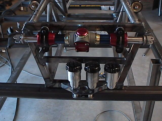
It's been a while since we posted some images, so here's a few more of the front of the chassis with the shocks, steering box and master cylinders in their places. At this point the chassis itself is about 90% complete.
The body plug is moving along but is in a "non-photogenic" state right now. It is about 90% covered in two layers of epoxy/glass, but we used a dye on the second layer (as a guide) to ensure we don't sand throught the epoxy and expose any foam....and it isn't very uniform in color. Once we get it looking a bit prettier we'll take a few shots.
Matt Conrad
Phoenix Race Cars, Inc.
The chassis for the new F1000 is essentially complete. About the only things we have left will be to mount small tabs for mounting the bodywork (once the bodywork is complete) and the seatbelt mounts.
Here's the front half....
....and the back half.....
FYI....the weight is showing 99 pounds. 72 pounds for the front half (roll hoop forward) and 27 pounds for the rear. SolidWorks showed 94 pounds (tubes only...no tabs, etc.) so we're pretty pleased. Just to re-iterate, all round tubes in the chassis are 4130 Cr/Mo and the square tubing (mainly the floor) is mild steel.
Matt Conrad
Phoenix Race Cars, Inc.


So, Matt. Will you have one ready for me when I'm out there in March?
Mike Beauchamp
RF95 Prototype 2
Get your FIA rain lights here:
www.gyrodynamics.net/product/cartek-fia-rain-light/
Absolutely....
Depending on your schedule, you may be able to see the car run as we have a few dates penciled in for running the car. There's two PASA events at FIR East (first and last weekends) and then the SCCA Double Nat at FIR Main on the weekend of the 10th.
We won't run the Double National unless we get a few good shakedown runs on the car prior....so we'll see.
Matt Conrad
Phoenix Race Cars, Inc.
FYI...in response to a few direct questions about how the 99 pound F1K-07 chassis compared to our SR chassis....the original bare Maloy chassis weighed 125 pounds and the updated SR-07 chassis weighed 121 pounds.
We've been posting alot of "big-picture" stuff on the new car, but I want to start doing some posts on some details on the new Phoenix F1K-07 that might get overlooked as we discuss the car.
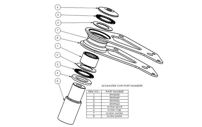
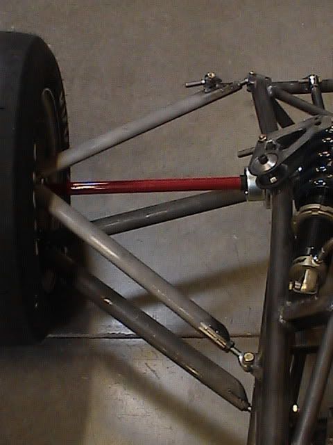
The first item would be the bell cranks. We originally intended to use a billet aluminum part which would be designed to be used on all 4 corners of the car, but when we analyzed cost, weight and performace....the billet aluminum piece lost out to a simple fabricated steel assembly.
Here's the part without bearings:
All of the parts are waterjet cut (except for the bearing housing, obviously which is machined) and once fully welded they weigh in at only 15 oz. As in our original intent with the billet part, they are the same on all 4 corners. For reference, the bare Maloy rocker (also steel) weighs 23 oz.
It may not have the same "wow factor" as a billet aluminum part, but it will perform as well, is as light, and the low cost will help us in our goal to deliver a complete turn-key car for $42,900.
Matt Conrad
Phoenix Race Cars, Inc.
"See" the car run? I was hoping for some seat time!Originally Posted by Matt Conrad


Mike Beauchamp
RF95 Prototype 2
Get your FIA rain lights here:
www.gyrodynamics.net/product/cartek-fia-rain-light/

Matt,
I wonder if you would share with us why your frame does not have a raised footbox area, like so many current racecars? I understand if you don't want to reveal something.

I‘m not Matt, but I think that I can field this one….
We have several reasons for a foot box that is not raised; here is a short list…..
Better load paths (Stiffness V. Weight)
A-arm packaging
Safety
Cost
Ease of fabrication
Rules…
…and here is an in depth explanation; in other words, all our secrets revealed.
The chassis was designed under the school of the thought that stiffness is paramount. Not only is the overall all torsional stiffness of the chassis important, but so too are all the “localized” stiffness. Localized stiffness is a term that we have begun to use in regard to the stiffness of each of the suspension mounting points. The front lower A-arm mounts attached directly to the bottom frame rail, this makes for a stiff and light assembly that is easy to fabricate. The A-arm mounts are also intended to prevent A-arm intrusion, so they are placed at nodes (the place where many tubes join together) and are boxed, per rules.
Since the whole bottom of the chassis is coplanar a single sheet metal stressed bottom panel can be water jet cut. One panel can be bonded and riveted all in a single step with fewer seams. And since there are fewer seams a potential for better stiffness. A single unbent panel has obviously less cost in fabrication.
We wanted a very robust foot box in the event of a front end collision. It was intended to have a set of straight load paths from the front of the chassis to the rear. A raised foot box would have added an extra complication in this manner. A step in the chassis would have resulted in a step in the load paths. To solve the load path step problem more tubes / gussets might be used and so more weight added to the chassis.
To further the attempt at front end impact safety, the driver’s feet are well behind the rules mandated front of the rims. In fact the front bulk head itself is only 2” in front of the front axel center line, meaning that every driver will be seated with his/her feet behind the front axle.
We might be interpreting the rules incorrectly, but our understanding was that the floor could not deviate more then 1”. This rule truncates any raised foot box to either the rear edge of the front tier, or 1”. Neither option proved very beneficial aerodynamically.
We wanted to keep the drivers feet, master cylinders, pedals, steering rack, and ext. as low as possible. These components might not be that heavy, but every little cg advantage adds up.
I will probably read this post tomorrow, after sleeping, and edit it for content and grammar. I apologize to any who might read it before then, hope you were able to understand my late night babble.
One last thing, I encourage you all to ask technical questions, I will answer any I can. My thoughts are that you guys are quite smart, and questions you ask will help make us better at a faster rate then if we were left to our own devices. Bring on those ?’s lets all learn together.
Thanks
Dustin Wright
Last edited by Wright D; 01.12.07 at 9:38 PM. Reason: oops, I ment revealed.
Lee,
Yea....what he said....and as you notice from Dustin's response....we have no secrets.
FYI, for those that don't know.....Dustin Wright is the designer of the car.
Matt Conrad
Phoenix Race Cars, Inc.

You guys have really done a great job in designing this car...
However, I disagree with the last word in this sentence:
"…and here is an in depth explanation; in other words, all our secrets reviled."
It seems like all your secrets are revealed, which is a different approach than other mfg have, kinda like what is hapening with open-source software.
I feel sure that most of us here feel that your work is greatly admired and revered.
Keep the updates coming...

Very nice report, Dustin...thanks for sharing it with us!
And yes, you are misinterpreting the rules, as there is no requirement that the floor not deviate by more than 1". That issue was the subject of extended conversation last year, but did not make the final cut of the rules. No harm done, though, as your design appears very well thought out.
Thanks again! Stan
Stan Clayton
Stohr Cars
Stan,
That "extended conversation" was just one of the factors that we discussed in our initial meetings on the car design.
....and I believe Dustin meant to type "revealed" and not "reviled". As you notice by our many posts......It is our approach on this F1000 car (and future designs as well) to be very "public" with what we are doing. We may not share every little detail, but we're not building a secret stealth fighter here. This forum was extremely helpful to me when I began racing in FC and I learned a great deal from the members who were almost always willing to share their experience and knowledge with me without hesitation.
Matt Conrad
Phoenix Race Cars, Inc.
Stan,
Did you mean to say that there is no rule requiring the frame not deviate by more than an inch?
Lee, I was referring to the last sentence in paragraph D.6.d. of page 199 of the 2007 GCR, which reads, "Its curvature shall not exceed one inch." That rule does not apply to F-1000. Sorry if that was not clear. Stan
Stan Clayton
Stohr Cars
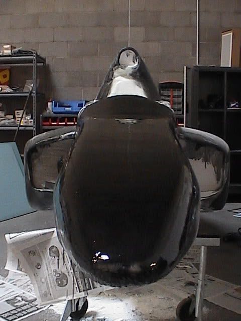
Now that the plug is covered in 2 layers of glass and epoxy the body filler has begun to fly and the real fun begins....I just love the smell of Bondo in the morning!
And even though it's not real pretty....we've decided to post some pictures of the progress. Here goes....Nice and shiny as the epoxy (dye'd black) goes on....
and now we've begun the first bit of sanding prior to adding the body filler.....
You may notice that the sidepod inlets have been modified from our original design (triangular) to a more square opening. These are the "max" openings and our new design calls for inserts which can be added to change the amount of air to the coolers when limited cooling is desired.
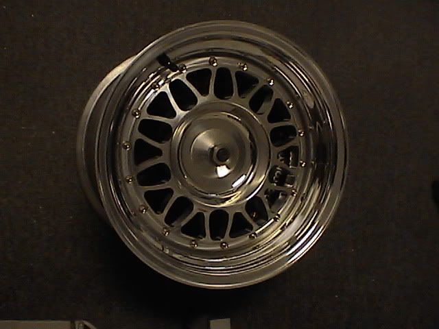
We also received the wheels for the car today and that was a reminder to me to make sure we announce that we have made a change to our original specifications for the car and will be using Kodiak Wheels. Here's a photo....
These are one of the current designs offered by Kodiak, but plans for the production car are for a newly designed wheel....more later.
Matt Conrad
Phoenix Race Cars, Inc.
Could you tell me what are type and size of bearings do you plan to use in this bellcrank and what do you anticipate will be their service life?
regards,
Neil Roshier
Publisher
Race Magazine
Neil & Others,
The main pivot bearings are 1" ID needle roller bearings. There are also trust type needle roller bearings on each side of the assembly.
Here is an exploded picture of the assembly.
As far as the life span, I would expect that the assembly will have a similar life span to others like it.
The bearings are available through McMaster Carr; just look them up with the numbers in the drawing if you would like more specific information.
Dustin Wright
Last edited by Wright D; 01.22.07 at 12:36 AM. Reason: had to change OD to ID, big difference
Thank you Dustin, I had wonderd if they were 'Nadella' bearings. This is actually a brand name, but it is common to refer to their combined needle roller radial/axial bearing as such.
I am packaging a different type of car at the moment and am keen to use a bellcrank, but suitable bearings are proving troublesome as stiction becomes such an issue. I was also looking at opposed and spaced tapered needle roller bearings as a solution. What other solutions have you seen?
There is no need to send the specific details as my application is no the same...I am looking at 100mm of rebound and 85mm of jounce.
Regards,
Neil Roshier
Publisher
Race Magazine
I have seen tapered rollers used as rocker bearings, and to be frank, I don’t like them. Tapered rollers tend to be heavy, and difficult to adjust. When I say adjust, I mean the preload in the bearings. If it is too much then there is undo friction, to little and the rocker wobbles. I have also seen angular contact ball bearings, but have the same adjustment and weight issues that the tapered rollers do.
The angular contact ball bearings and tapered roller units have very large outer diameters compared to their inner diameter. In other words their OD/ID is very large. The needle bearing units have an OD/ID that is considerably smaller. Use of a needle type over the others allows for a larger pivot shaft and smaller bearing housing. The larger pivot shaft increases assembly stiffness, and the smaller bearing housing reduces weight. The needle bearing units are much lighter then the other two types as well. So; there are weight savings in several areas, increased stiffness, easier to install and set preload…. Oh and they cost less too.
I have a pretty one sided opinion on the matter, as you might have read, but I prefer the needle type.
Anyone else prefer another type?
Dustin Wright
Dustin:
Since you asked, I have used 15 mm ID light section ball bearings for rocker arms and bell cranks, I have the pins supported in double shear. For single shear I have gone to 17 mm ID light section bearings. My design does have a 3/8" bolt through entire the pin so the bearing inner races and spacer are part of the support structure.
In 1995 we did a lot of work on the bell crank layout. We did try tapper rollers. The tapper rollers worked well but it was a real pain to get setup correctly.
The 15mm ID bearing setup has given good service. We have bent 1 pin in 20 years of service. We have never had a bearing failure and have had cars in service 20 years.
I did use the 1 inch needle rollers in the Zink Z10 rockers.
From the look of your bell crank, it appears that you are able to machine the bearing support and weld it to the bell crank without having to finish the bearing bore afterwords. Correct?
Yep...the ones in my Z10 are still working flawlessly after 30 years of service.I did use the 1 inch needle rollers in the Zink Z10 rockers.
Stan Clayton
Stohr Cars
Matt,Dustin, just wanted to thank you guys for posting your idea for w j cutting the sections for your model we have a small job coming in that happens to have cad data for a change ( other wise we work from sketches etc,)and I'm anxious to try your system but we will be using polyisocyanurate foam and sealing it with poly resin and mat,noworries about solvent erosion. Your model is coming along nicely now you get to split the moulds great fun!
btw; would you guys mind if I contact you directly? my site http://preformresources.com/
Thanx,Dave Craddock
Stan:
There is nothing in the rocker or bell crank application that is good for these bearings, I doubt that the rocker or bell cranks ever rotate the rollers in the bearings a single revolution per movement. Most of the movements just squish the lubricants out from the bearing surfaces.
Isn't it wounderful that the builders of these components produce products that that defy all logic and survive our abuse.
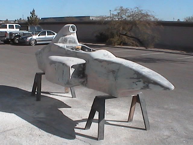
Well, after many, many, many (did I say many) hours of sanding, scraping and shaping it is ready to go to the paint shop for some more sanding and a few coats of Laminex. We really focused on the critical shaping areas (rad scoops, air intake) and making sure the car was very symmetrical.
Many of you will notice the changes from our original concept images....mainly the real car has more square rad intakes vs. the original triangular shape and we added some curvature into the top of the nose vs. the original shape which was much more flat. Both of those changes were mainly for aesthetics, and not from any CFD testing.
We'll now let the professionals apply the finishing touches and a mirror-like finish.
Even though using the waterjet cut foam saved us a few weeks, it was still a ton of work to get to this stage. One big benefit to the foam though is that the whole thing weighs about 200 pounds....not bad. And as an FYI....it is actually taller than the real body will be because we built up the bottom by a few inches. I'm told we should have it back by next weekend and our mold-maker can then start doing his thing.
In the meantime, our symmetrical, streamlined tube a-arms are being assembled and we'll be test fitting the tacked-up parts early next week. They fit in the computer, and we've verified the measurements on the real chassis, but we just want to be 100% sure. Once we are, we'll have the jigs and parts finish welded and we'll have a suspended chassis. We will not install the anti-intrusion bars on until the bodywork is done. Hopefully pics of the finished plug and a suspended chassis by next weekend????
Matt Conrad
Phoenix Race Works, LLC
Last edited by Matt Conrad; 01.26.07 at 3:07 PM. Reason: Added changes note....
What was written here I might regret!
Last edited by Jonathan Speed; 01.27.07 at 3:37 AM. Reason: re-thought
Jonothan,
I don't know what was written before you changed it....but please understand that we have made the decision to show our car in every stage of construction....pretty or not.....and it is not pretty right now. But it is a part of the process. The mold-making process may even be uglier, but we'll probably show that too.
We also know showing the plug without having the wings, tires and wheels, floor and suspension around it isn't very flattering as well. This is an older photo before we began on the sanding of the plug. It still doesn't have the wheel kick-ups, suspension or the floor, but it should give you a better visual of the car.
Matt Conrad
Phoenix Race Works, LLC

Matt,
I don't know what was written either but this is a development project and there will be many parts of that process that will be ugly.
I for one appreciate you sharing it with us.
Thanks Dave....
One big benefit of exposing the build is that we get feedback from the public....some good and some not so good....but for us it's all good because it has helped us build a better car.
Here's a perfect example....one person (a car designer) suggested a change to the area just in front of the cockpit....and we are going to implement it. It doesn't change the aero...just helps with the aesthetics of the car. Here's a touched-up image showing the modification....
It may push us back a day...but I think it's worth it....
Matt Conrad
Phoenix Race Works, LLC

The front looks like a shark, while the whole car if it had wings, would look like a jet fighter. These are positive comments as a "shark" looks very mean, while the jet fighter implies "speed". Mean with speed. What a combination.
As I see this project unfolding, one must think of the enormous amount of time, design and decision making that must go into a new car.
Thanks for keeping of all us posted, its fun for us, and can't imagine of much fun it is for the manufacturer.
Richard Dziak
Las Cruces, New Mexico
Former Phoenix F1K-07 F1000 #77 owner/driver
website: http://www.formularacingltd.com
email: sonewmexico@gmail.com
I think the modification will be well worth the extra day! Just that one change makes all the difference in the world. Matt isn't there a program where you can take the current photo and establish a fairly realistic image of the new car?

Actually Clark Lincoln did the modification to the the photo and he is capable of completing the process. He has done a number these types of these renderings in the past.
So that I don't hijack the thread some examples are on the Sport Racer Forum
http://p081.ezboard.com/fdsrforumcar...tart=1&stop=20
See Clarks posting "more eye candy'
Mike Devins
I've spoken to Clark this weekend and if we have the time I may see if we can do up a professional looking rendering of the car as it will look in race trim. More Later.
Matt Conrad
Phoenix Race Cars, LLC
Anyone have Clark's contact info?
Thanks
Eric, Clark's cell # is 586-337-1941
Thanks Dave!
Matt
What is the assumed seat angle in your car?
Thanks
Todd
Todd,
I guess I'm not exactly sure what you're looking for....but the angle of the seat back panel (which houses the fuel cell) is 45 degrees. The angle of how a driver is seated can be adjusted based on how the driver seat is shaped and the size of the driver. If you're not familiar, these cars don't have a seat per se...you pour a seat into the cockpit which contours to fit the driver.
Our design allows multiple locations for the foot pedals so adjustments to positioning can be made fairly easily. Our cockpit is fairly large (but not quite as large as the Maloy) and can accomodate a wide variety of drivers.
Hope I answered your question.
Matt Conrad
Phoenix Race Works, LLC
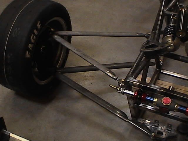
The new streamlined aero tube suspension parts were finished yesterday and we got them all mounted up last night. They fit pretty good...only a couple minor adjustments required.....Here's the front:
and here's the rear:
The arms are only tacked together (just in case) and obviously we don't have the pushrods, toe links and steering links attached yet, but we've now verified all those measurements off the real suspension and now we can weld evrything up and we'll have the rolling chassis soon. The front anti-intrusion bars will not be added until the bodywork is on. The suspension arms will also be coated with "ProCoat" once they are finished. This is a baked on finish similar to what you'll see on gun barrels.
Matt Conrad
Phoenix Race Works, LLC
Last edited by Matt Conrad; 02.01.07 at 12:17 PM. Reason: typo
There are currently 1 users browsing this thread. (0 members and 1 guests)
 Posting Permissions

 Reply With Quote